Bluetooth Low Energy (BLE) is a low power wireless technology used for connecting devices with each other. It is a popular communication method especially in the era of Internet of Things. Several devices around the house have a build-in buetooth transceiver and most of them provide really useful capabilitites to automate jobs. For that reason it is really interesting to create desktop application using C# that connects to the devices around the house and manage them.
In this example we are going to create a simple C# windows form application to communicate with BleuIO using SerialPort. This script can be used to create Bluetooth Low Energy application using C# with BleuIO.
Let’s start
As a first step lets create a new project in visual studio and select C# windows form application from the list.
Choose a suitable name for your project.
Once the project is created, we will see a blank form screen where we will add buttons and labels to communicate with BleuIO graphically.
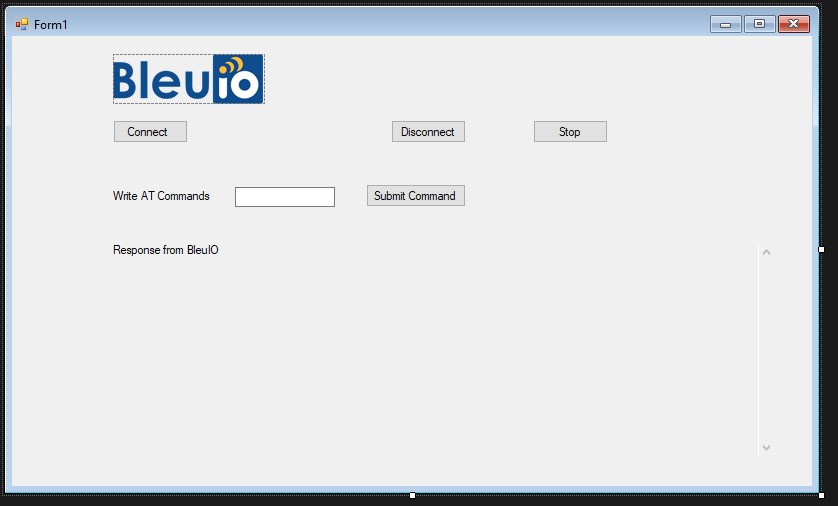
We will have buttons that connects and disconnects from BleuIO. An input field that takes AT commands from the user and sends it to BleuIO using SerialPort. And a text area will display the response from BleuIO to the screen.
The form will look like this
The .cs file associated to this will have the following code.
Source code is available at https://github.com/smart-sensor-devices-ab/bluetooth_low_energy_csharp_WFA.git
using System;
using System.IO.Ports;
using System.Linq;
using System.Text;
using System.Windows.Forms;

namespace WindowsFormsApp1
{

    public partial class Form1 : Form
    {
        SerialPort mySerialPort = new SerialPort("COM18", 57600, Parity.None, 8, StopBits.One);
        public Form1()
        {
            InitializeComponent();
            mySerialPort.DataReceived += new SerialDataReceivedEventHandler(mySerialPort_DataReceived);
            mySerialPort.Open();

        }

        private void button1_Click(object sender, EventArgs e)
        {


            lbl_test.Text = "Connected";
        }

        //print response from the dongle
        private void mySerialPort_DataReceived(object sender, SerialDataReceivedEventArgs e)
        {
            SerialPort sp = (SerialPort)sender;
            string s = sp.ReadExisting();
            output_data.Invoke(new EventHandler(delegate { output_data.Text +=  s + "\r\n"; }));

            //lbl_output.Invoke(this.myDelegate, new Object[] { s });
        }


        private void tb_cmd_TextChanged(object sender, EventArgs e)
        {

        }

        private void submit_cmd_Click(object sender, EventArgs e)
        {
            output_data.Text = "";
            byte[] bytes = Encoding.UTF8.GetBytes(tb_cmd.Text);
            var inputByte = new byte[] { 13 };
            bytes = bytes.Concat(inputByte).ToArray();
            mySerialPort.Write(bytes, 0, bytes.Length);
        }

        private void btn_disconnect_Click(object sender, EventArgs e)
        {
            mySerialPort.Close();
            Environment.Exit(0);
        }

        private void Form1_Load(object sender, EventArgs e)
        {

        }

        private void btn_stop_Click(object sender, EventArgs e)
        {
            byte[] bytes = Encoding.UTF8.GetBytes("\u0003");
            var inputByte = new byte[] { 13 };
            bytes = bytes.Concat(inputByte).ToArray();
            mySerialPort.Write(bytes, 0, bytes.Length);
        }

        private void output_data_TextChanged(object sender, EventArgs e)
        {

        }

        private void pictureBox1_Click(object sender, EventArgs e)
        {

        }
    }
}
As you can notice I wrote COM18 to connect to serial port because BleuIO device on my computer is connected to COM18.
You can check your COM port from device manager.
Lets run the project and click on connect button.
Once we are connected to BleuIO, we will be able to write AT commands using the input filed.
List of AT commands are available at https://www.bleuio.com/getting_started/docs/commands/
There is a stop button that write control+c to dongle and cancels current execution.
Bluetooth Low Energy (BLE) is a low power wireless technology used for connecting devices with each other. It is a popular communication method especially in the era of Internet of Things. Several devices around the house have a build-in buetooth transceiver and most of them provide really useful capabilitites to automate jobs. For that reason it is really interesting to be able to create a main-device (like a PC) which will have an application that connects to the devices around the house and manage them.
In this example we are going to create a simple C# console application to communicate with BleuIO using SerialPort. This script can be used to create Bluetooth Low Energy application using C# with BleuIO.
Let’s start
As a first step lets create a new project in visual studio and select C# console application from the list.
Choose a suitable name for your project and paste the following code to Program.cs file.
Protection of private information is essential for every wireless low energy device, from fitness bands to payment systems. Privacy mechanisms prevent devices from being tracked by untrusted devices.
Secure communications keep data safe while also preventing unauthorized devices from injecting data to trigger the system’s unintended operation.
In Bluetooth Low Energy (BLE), devices connected to a link can pass sensitive data by setting up a secure encrypted connection, which means making the data unreadable to all but the Bluetooth master and slave devices.
A BLE connection is said to operate at a specific Security mode. Within each mode are several security levels. The required security mode/level of a connection may change from time to time, leading to procedures to increase that level.
To keep it simple, when two devices that initially do not have security wish to do something that requires security, the devices must pair first. This process could be triggered, for example, by a central device that is attempting to access a data value (a “characteristic”) on a peripheral device that requires authenticated access.
Pairing involves authenticating the identity of two devices, encrypting the link using a Short-Term Key (STKs), and then distributing Long-Term Keys (LTKs) (for faster reconnection in the future, i.e., bonding) used for encryption.
The new security level of the connection is based on the method of pairing performed and this is selected based on the I/O capabilities of each device. The security level of any subsequent reconnections is based on the level achieved during the initial pairing.
Each device’s role is defined in the Security Manager (SM) portion of the BLE stack. They are:
Initiator: Always corresponds to the Link Layer Master and the GAP central.
Responder: Always corresponds to the Link Layer Slave and the GAP peripheral.
Security by means of encryption contains four levels
Level 1: No Security (No authentication and no encryption)
Level 2: Unauthenticated pairing with encryption
Level 3: Authenticated pairing with encryption
Level 4: Authenticated LE Secure Connections pairing with encryption
BleuIO has introduced a security feature into its latest release (firmware v2.1.1 ) which handles all four security levels to establish a secure BLE connection. Users can now use Numeric Comparison, Just Works or Passkey Entry to make data transmission more secure when working with Bluetooth low energy applications using BleuIO.
Numeric Comparison: In this scenario, both devices have a display unit capable of displaying a six-digit number. Both displays output the same number, and the user is asked to confirm that these numbers match.
Passkey Entry: The Passkey Entry is primarily intended for the case that one device has a keyboard, but no display unit and the other device has at least a display unit, for example, a PC and a BLE keyboard scenario. The user is shown a six-digit number (from “000000” to “999999”) on the device with a display and then is asked to enter the number on the other device. If the value entered on the second device is correct, the pairing is successful.
Just Works: This model is primarily intended for the most constrained devices in I/O. The Just Works association model uses the Numeric Comparison protocol, but the user is never shown a number, and the application may ask the user to accept the connection. This method doesn’t offer protection against a Man in the Middle (MITM) attack, but it provides the same protection level against passive eavesdropping as the Numeric Comparison.
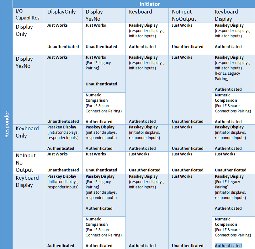
The table below is a reference for determining the pairing method based on the two devices I/O capabilities and each device’s role in the process.
Use the following AT commands to make your BLE connection more secure.
AT Commands :
AT+SETPASSKEY for setting or querying set passkey for passkey authentication.
AT+SECLVL for setting or querying minimum security level used when connected to other devices.
AT+NUMCOMPA accepts a numeric comparison authentication request or enables/disabling auto-accepting numeric comparisons.
AT+GAPADDRTYPE Sets or queries what address type the dongle will use. Changing address type cannot be done while advertising or while connected to other devices. Read more at https://www.bleuio.com/getting_started/docs/commands/#atgapaddrtype
BleuIO Javascript library is updated and supports firmware version 2.1.0
Now you can easily access all the BleuIO AT commands from web browser using this library.
Before starting to install our library, make sure you have Chrome 78 or later version installed on your system. You will also need to enable the #enable-experimental-web-platform-features flag in chrome://flags. To do that, Open chrome://flags/#enable-experimental-web-platform-features in Google Chrome browser and enable this feature.
You can use chrome.serial to create web apps that can access the BleuIO AT commands easily using this library.
Now Install the library by running
npm i bleuio
npm automatically downloads and installs the most recent library on your system in the correct directory. To check that the installation went well, follow the simple readme file from
Home automation involves automating household environment equipment. To achieve that, we have created a smart bulb that is easy to install, and the attached equipment can be controlled over a web browser or smartphone app. The aim of this project is to control different home appliances using a web browser or smartphone.
1. Introduction
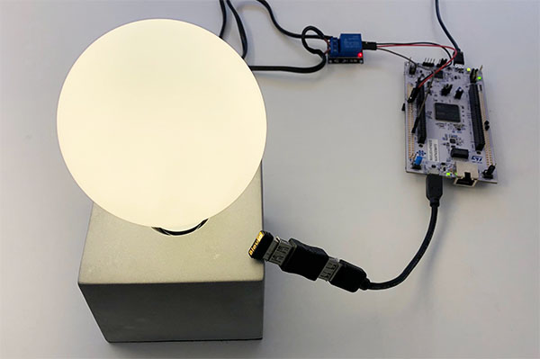
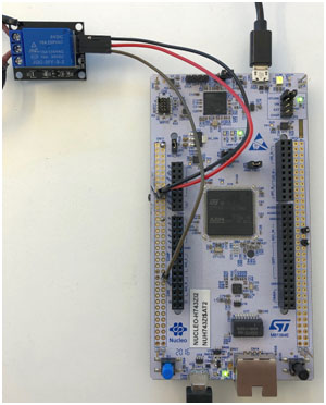
The project is showcasing a simple way of using the the BleuIO Dongle to turn on and off a light bulb that is connected to the STM32 Nucleo-144 via a 5V Relay.
You will need two dongles, one connected to the Nucleo board and one connected to a computer, running the web script. When the BleuIO Dongle is connected to the Nucleo boards USB port the STM32 will recognize it and directly start advertising. This allows the other Dongle to connect to it.
It will also accept 3 different inputs from the UART:
input
result
0
Send ATI (Request device information) command to BlueIO Dongle.
1
Manually turn the light bulb on
2
Manually turn the light bulb off
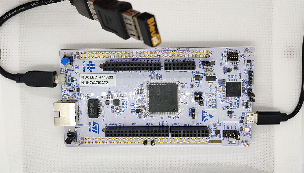
We have used a STM32 Nucleo-144 development board with STM32H743ZI MCU (STM32H743ZI micro mbed-Enabled Development Nucleo-144 series ARM® Cortex®-M7 MCU 32-Bit Embedded Evaluation Board) for this example.
If you want to use another setup you will have to make sure it support USB Host and beware that the GPIO setup might be different and may need to be reconfigured in the .ioc file.
WARNING – THIS PROJECT INVOLVES HIGH VOLTAGES THAT CAN CAUSE SERIOUS INJURY OR DEATH. PLEASE TAKE ALL NECESSARY PRECAUTIONS, AND TURN OFF ALL POWER TO A CIRCUIT BEFORE WORKING ON IT.
2. Connecting the relay
Beware:
Always be very careful when experimenting with AC, electrical shock can result in serious injuries! NOTICE OF RISK; DISCLAIMER OF LIABILITY
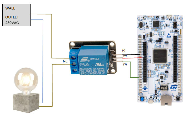
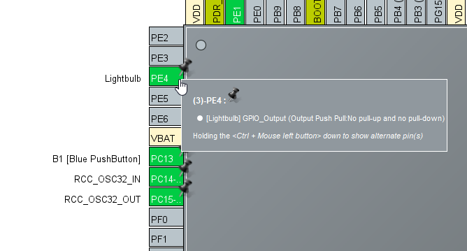
Pinout and Connection to STM32 For the DC part of the Relay circuit connect S (signal) to pin PE4 on the STM32 NUCLEO board, also connect the Power supply (+) and ground (-) to +5V and GND respectively.
In the pinout view we set the GPIO PE4 to OUTPUT and labeled it to ‘lightbulb’.
In the USBH_CDC_ReceiveCallback function in USB_HOST\usb_host.c we copy the CDC_RX_Buffer into a external variable called dongle_response that is accessable from the main.c file.
void USBH_CDC_ReceiveCallback(USBH_HandleTypeDef *phost)
{
    if(phost == &hUsbHostFS)
    {
        // Handles the data recived from the USB CDC host, here just printing it out to UART
        rx_size = USBH_CDC_GetLastReceivedDataSize(phost);
        HAL_UART_Transmit(&huart3, CDC_RX_Buffer, rx_size, HAL_MAX_DELAY);

        // Copy buffer to external dongle_response buffer
        strcpy((char *)dongle_response, (char *)CDC_RX_Buffer);

        memset(CDC_RX_Buffer,0,RX_BUFF_SIZE);
        USBH_CDC_Receive(phost, CDC_RX_Buffer, RX_BUFF_SIZE);
    }

    return;
}
In main.c we create a simple intepreter so we can react to the data we are recieving from the dongle.
We put the intepreter function inside the main loop.
/* Infinite loop */
  /* USER CODE BEGIN WHILE */
  while (1)
  {
    /* USER CODE END WHILE */
    MX_USB_HOST_Process();

    /* USER CODE BEGIN 3 */
    // Simple handler for uart input
    handleUartInput(uartStatus);
    // Inteprets the dongle data
    dongle_interpreter(dongle_response);

    // Starts advertising as soon as the Dongle is ready.
    if(!isAdvertising && !isConnected && isBleuIOReady)
    {
        HAL_Delay(200);
        writeToDongle((uint8_t*)DONGLE_CMD_AT_ADVSTART);
        isAdvertising = true;
    }
  }
  /* USER CODE END 3 */
The script for the dongle (available on the source code inside web script folder)
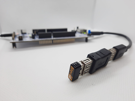
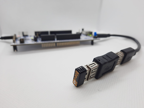
A board with a STM32 Microcontroller with a USB port. (A Nucleo-144 development board: NUCLEO-H743ZI2, was used developing this example. (https://www.st.com/en/evaluation-tools/nucleo-h743zi.html) To connect the dongle to the Nucleo board a “USB A to Micro USB B”-cable with a USB A female-to-female adapter can be used.)
Either clone the project, or download it as a zip file and unzip it, into your STM32CubeIDE workspace.
5.2 Importing as an Existing Project
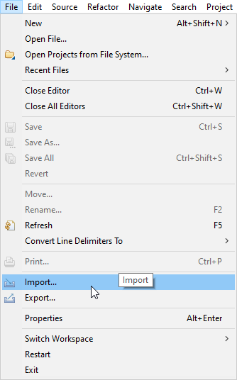
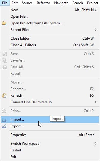
From STM32CubeIDE choose File>Import…
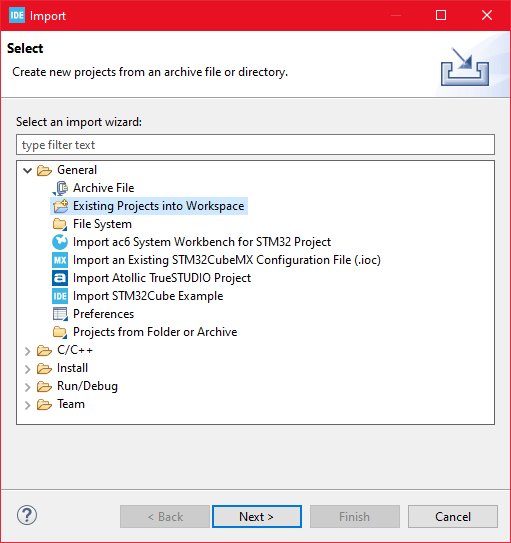
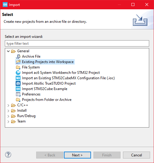
Then choose General>Existing Projects into Workspace then click ‘Next >’
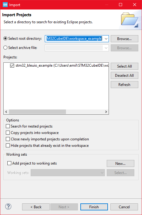
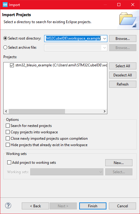
Make sure you’ve choosen your workspace in ‘Select root directory:’
You should see the project “stm32_bleuio_example”, check it and click ‘Finish’.
6. Running the example
In STMCubeIDE click the hammer icon to build the project.
Open up the ‘STMicroelectronics STLink Viritual COM Port’ with a serial terminal emulation program like TeraTerm, Putty or CoolTerm.Serial port Setup: Baudrate: 115200 Data Bits: 8 Parity: None Stop Bits: 1 Flow Control: None
Connect the BleuIO Dongle before running the example .
In STMCubeIDE click the green play button to flash and run it on your board. The first time you click it the ‘Run Configuration’ window will appear. You can just leave it as is and click run.
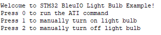
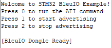
You should be greeted by this welcome message:
Wait until the message: “[BleuIO Dongle Ready]” is shown.
You can now connect with the other dongle using the script.
You can also use the uart commands (0, 1 or 2):
Press 0 to get device information.
1 to turn on lightbulb.
2 to turn off lightbulb.
Dongle response will be printed to UART.
7. Controlling the light from a web browser
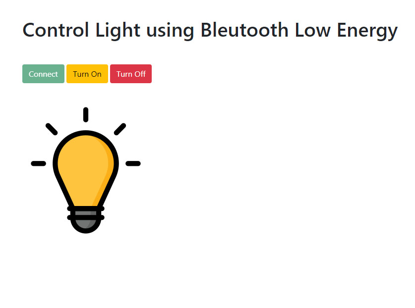
We wrote a simple script that connects to the dongle and sends signals to toggle the light from the web browser.
Create a simple Html file called index.html which will serve as the frontend of the script. This Html file contains some buttons that help connect and signal to the remote dongle, which is connected to stm32.
Create a js file called script.js and include it at the bottom of the Html file. This js file uses the BleuIO js library to write AT commands and communicate with the other dongle.
import * as my_dongle from "bleuio";
const dongleToConnect = "[0]40:48:FD:E5:35:A5";
import lightOnImg from "./light_on.png";
import lightOfImg from "./light_off.png";
document.getElementById("connect").addEventListener("click", function () {
  my_dongle.at_connect();
  document.getElementById("lightOn").disabled = false;
  document.getElementById("lightOf").disabled = false;
  document.getElementById("connect").disabled = true;
});

document.getElementById("lightOn").addEventListener("click", function () {
  my_dongle
    .ati()
    .then((data) => {
      //make central if not
      if (JSON.stringify(data).includes("Peripheral")) {
        console.log("peripheral");
        my_dongle.at_central().then((x) => {
          console.log("central now");
        });
      }
    })
    .then(() => {
      // connect to dongle
      my_dongle
        .at_getconn()
        .then((y) => {
          if (JSON.stringify(y).includes(dongleToConnect)) {
            console.log("already connected");
          } else {
            my_dongle.at_gapconnect(dongleToConnect).then(() => {
              console.log("connected successfully");
            });
          }
        })
        .then(() => {
          // send command to control light
          my_dongle.at_spssend("L=1").then(() => {
            console.log("Turned on");
            document.getElementById("light").src = lightOnImg;
          });
        });
    });
});

document.getElementById("lightOf").addEventListener("click", function () {
  my_dongle
    .ati()
    .then((data) => {
      //make central if not
      if (JSON.stringify(data).includes("Peripheral")) {
        console.log("peripheral");
        my_dongle.at_central().then((x) => {
          console.log("central now");
        });
      }
    })
    .then(() => {
      // connect to dongle
      my_dongle
        .at_getconn()
        .then((y) => {
          if (JSON.stringify(y).includes(dongleToConnect)) {
            console.log("already connected");
          } else {
            my_dongle.at_gapconnect(dongleToConnect).then(() => {
              console.log("connected successfully");
            });
          }
        })
        .then(() => {
          // send command to control light
          my_dongle.at_spssend("L=0").then(() => {
            console.log("Turned off");
            document.getElementById("light").src = lightOfImg;
          });
        });
    });
});
The script js file has three button actions; connect and control light.
Now we need to know the ID of the other dongle connected to STM32 so that we can connect to it. You can use this web terminal to get the dongle ID.
- Open this site https://bleuio.com/web_terminal.html and click connect to dongle.
- Select the appropriate port to connect.
- Once it says connected, type **"ATI"**. This will show dongle information and current status.
- If the dongle is on peripheral role, set it to central by typing **"AT+CENTRAL"**
- Now do a gap scan by typing **"AT+GAPSCAN"**
- Once you see your dongle on the list ,stop the scan by pressing control+c
- Copy the ID and paste it into the script (script.js) line #2
You will need a web bundler. You can use parcel.js
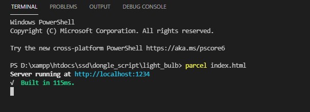
Once parcel js installed, go to the root directory and type “parcel index.html”. This will start your development environment.
Open the script on a browser using parcel js.
You can easily connect to the dongle and turn on-off light from there.
You can also access the script athttps://smart-sensor-devices-ab.github.io/stm32_bleuio_lightbulb_example/web%20script/dist/index.html
Smart Sensor Devices AB, a manufacturer and provider of IoT solutions, is pleased to announce that its Bluetooth low energy USB dongle called BleuIO will be available for immediate shipment worldwide through the Robotshop Marketplace.
The product is listed on RobotShop and available for purchase.
“Joining the RobotShop Marketplace is a strategic move that allows our Bluetooth Low Energy USB dongle BlueIO to be viewed and purchased with ease through RobotShop’s well established online process. Products will ship typically within 2 days of order placement from Smart Sensor Devices, Stockholm, Sweden. It’s a winning combination for Smart Sensor Devices, and we look forward to working with RobotShop.” said Axel G. Hammar, Founder & CEO, Smart Sensor Devices.
About BleuIO
This BleuIO is a Bluetooth low energy USB dongle that can create a new BLE 5.0 application in the fastest and easiest way. Just use the AT Commands available on the device. Details about the AT commands can be found on the getting started guide, which will help anyone make a fast peripheral or central application (or both) without developing a single line of embedded code.
It is a fully integrated solution, providing MCU and Bluetooth radio in one chip, based on Dialog Semiconductor latest Bluetooth chip DA14683. The FLASH based device permits field or boot upgradable, while the application is stored on FLASH memory. Custom settings can also be stored on FLASH memory or OTP for higher integrity. It supports Windows 10, Linux and macOS.
About Smart Sensor Devices
Smart Sensor Devices is a Swedish company working globally with the latest IoT solutions. We are located in Stockholm, the hottest hub for IoT inventions. Get in contact with us today and explore how you can become part of it! Our long-term experience in IoT devices and systems is crucial for giving your business the most for your investments, improving Time To Market, and lowering your risk.
About RobotShop
RobotShop operates globally and specializes in robotics technology. They offer a wide range of products and services in this sector. Since its founding in 2003, RobotShop is renowned as the most visited robotics website in the world, offering a variety of robotic goods, such as educational and professional robots, as well as mechanical and electronic parts and components. Apart from that, RobotShop’s website brings a large number of visitors. Its audience includes amateurs and professionals with a keen interest in emerging technologies, businesses, the education sector, as well as a large community promoting communication, mutual aid and technical support.
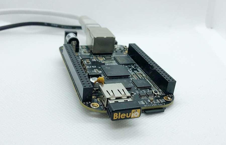
This is a simple example showcasing how to control a BleuIO dongle connected to Beaglebone Black using a python script.
When running the script, it will first ask for the com port where the dongle is connected (usually ‘/dev/ttyACM0’). After that, the BleuIO will start advertising. Every 8th second it will turn on one of the onboard Beaglebone Black LEDs whilst changing the BLE advertising name to indicate which LED is on.
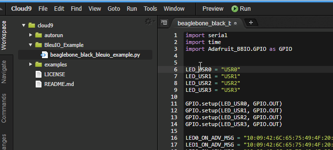
We are using the Adafruit_BBIO python library that comes with the Beaglebone to control the onboard LEDs. First we define the LEDs names and then set them as GPIO Outputs. Then we define the advertising messages that the BleuIO will switch between. Lets break one down:
“10” is the size of the advertising packet in HEX. “09” is the flag for device name (Complete Local Name). “42:6C:65:75:49:4F:20:4C:45:44:20:30:20:4F:4E” is the packet itself, translated from HEX to ASCII it says: “BleuIO LED 0 ON”
Afterwards the user is presented with a message to input the com port the BleuIO is connected to. If you are not using a USB Hub the port should be ‘/dev/ttyACM0’.
You can change the comport name in the Python script and fill in your COM port.
com_input = "/dev/ttyACM0"
The script continues into the main loop, where it will first make sure all LEDs are off and then start BLE advertising.
The loop iterates through all four LEDs. In every iteration it turns one LED on and advertise the LED name then continue to the next LED. This will continue until the script is aborted.
import serial
import time
import Adafruit_BBIO.GPIO as GPIO


LED_USR0 = "USR0"
LED_USR1 = "USR1"
LED_USR2 = "USR2"
LED_USR3 = "USR3"

GPIO.setup(LED_USR0, GPIO.OUT)
GPIO.setup(LED_USR1, GPIO.OUT)
GPIO.setup(LED_USR2, GPIO.OUT)
GPIO.setup(LED_USR3, GPIO.OUT)

LED0_ON_ADV_MSG = "10:09:42:6C:65:75:49:4F:20:4C:45:44:20:30:20:4F:4E:"
LED1_ON_ADV_MSG = "10:09:42:6C:65:75:49:4F:20:4C:45:44:20:31:20:4F:4E:"
LED2_ON_ADV_MSG = "10:09:42:6C:65:75:49:4F:20:4C:45:44:20:32:20:4F:4E:"
LED3_ON_ADV_MSG = "10:09:42:6C:65:75:49:4F:20:4C:45:44:20:33:20:4F:4E:"

# Turn off all LEDs
GPIO.output(LED_USR0, GPIO.LOW)
time.sleep(0.1)
GPIO.output(LED_USR1, GPIO.LOW)
time.sleep(0.1)
GPIO.output(LED_USR2, GPIO.LOW)
time.sleep(0.1)
GPIO.output(LED_USR3, GPIO.LOW)
time.sleep(0.1)

print("\nBlueIO BeagleBone Example!\n\n")
connecting_to_dongle = 0
com_input = ""

start_input = 0
valid_input = 0
while start_input == 0:
    com_input = input(
        "Enter Com port of Dongle (default for BeagleBone: '/dev/ttyACM0'):\n>>"
    )
    print("\nComport to use: " + com_input)
    input_continue = input(
        "If your happy with your choice just press Enter to continue the script. Else type E to exit or R to redo your choice. \n>>"
    )
    if input_continue.upper() == "E":
        start_input = 1
    elif input_continue.upper() == "":
        start_input = 1
    elif input_continue.upper() == "R":
        valid_input = 0
        start_input = 0
if input_continue.upper() == "E":
    print("Exiting script...")
    exit()

console = None

while 1:
    try:
        print("Please wait...")
        time.sleep(0.5)
        console.write(str.encode("AT+DUAL"))
        console.write("\r".encode())
        time.sleep(0.5)
        print("Starting Advertising...")
        console.write(str.encode("AT+ADVSTART"))
        console.write("\r".encode())
        time.sleep(0.5)
        led_turn = 0
        # Turn off all LEDs
        GPIO.output(LED_USR0, GPIO.LOW)
        time.sleep(0.1)
        GPIO.output(LED_USR1, GPIO.LOW)
        time.sleep(0.1)
        GPIO.output(LED_USR2, GPIO.LOW)
        time.sleep(0.1)
        GPIO.output(LED_USR3, GPIO.LOW)
        time.sleep(0.1)
        while True:
            if led_turn == 0:
                print("\nTurning LED USR0 ON")
                console.write(str.encode("AT+ADVRESP="))
                console.write(LED0_ON_ADV_MSG.encode())
                console.write("\r".encode())
                GPIO.output(LED_USR0, GPIO.HIGH)
                GPIO.output(LED_USR1, GPIO.LOW)
                GPIO.output(LED_USR2, GPIO.LOW)
                GPIO.output(LED_USR3, GPIO.LOW)
                led_turn = led_turn + 1
            elif led_turn == 1:
                print("\nTurning LED USR1 ON")
                console.write(str.encode("AT+ADVRESP="))
                console.write(LED1_ON_ADV_MSG.encode())
                console.write("\r".encode())
                GPIO.output(LED_USR0, GPIO.LOW)
                GPIO.output(LED_USR1, GPIO.HIGH)
                GPIO.output(LED_USR2, GPIO.LOW)
                GPIO.output(LED_USR3, GPIO.LOW)
                led_turn = led_turn + 1
            elif led_turn == 2:
                print("\nTurning LED USR2 ON")
                console.write(str.encode("AT+ADVRESP="))
                console.write(LED2_ON_ADV_MSG.encode())
                console.write("\r".encode())
                GPIO.output(LED_USR0, GPIO.LOW)
                GPIO.output(LED_USR1, GPIO.LOW)
                GPIO.output(LED_USR2, GPIO.HIGH)
                GPIO.output(LED_USR3, GPIO.LOW)
                led_turn = led_turn + 1
            elif led_turn == 3:
                print("\nTurning LED USR3 ON")
                console.write(str.encode("AT+ADVRESP="))
                console.write(LED3_ON_ADV_MSG.encode())
                console.write("\r".encode())
                GPIO.output(LED_USR0, GPIO.LOW)
                GPIO.output(LED_USR1, GPIO.LOW)
                GPIO.output(LED_USR2, GPIO.LOW)
                GPIO.output(LED_USR3, GPIO.HIGH)
                led_turn = 0

            time.sleep(8)

    except KeyboardInterrupt:
        GPIO.output(LED_USR0, GPIO.LOW)
        time.sleep(0.1)
        GPIO.output(LED_USR1, GPIO.LOW)
        time.sleep(0.1)
        GPIO.output(LED_USR2, GPIO.LOW)
        time.sleep(0.1)
        GPIO.output(LED_USR3, GPIO.LOW)
        time.sleep(0.1)
        print("Exiting script...")
        exit()
    except:
        print("\n\nDongle not connected.\n")
        connecting_to_dongle = 0
        while connecting_to_dongle == 0:
            try:
                print("Trying to connect to dongle...")
                console = serial.Serial(
                    port=com_input,
                    baudrate=57600,
                    parity="N",
                    stopbits=1,
                    bytesize=8,
                    timeout=0,
                )
                if console.is_open.__bool__():
                    connecting_to_dongle = 1
                    print("\n\nConnected to Dongle in port: " + com_input + ".\n")
            except:
                print(
                    "Dongle not found. Retrying connection to port: "
                    + com_input
                    + "..."
                )
                time.sleep(5)
The project is a simple example showcasing a quick way to setup an Arduino with a USB Host Shield as a USB CDC Host capable of communicating with the BleuIO Dongle.
When a BleuIO Dongle is connected to the USB port, the BleuIO Dongle will start advertising. It will then act as a terminal, taking input and sending data to the Arduino Virtual Com Port.
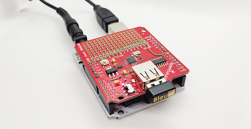
We have used an Arduino Uno Rev. 3 with SparkFun’s USB Host Shield (DEV-09947) for this example.
The largest possible max.packet size for the function Acm.RcvData() is 64 bytes, so to accommodate the amount of data we will receive, we are using three buffers to receive the data from the BleuIO Dongle.
If the buffers have received any data, we print it out to the serial terminal connected to the Virtual COM Port.
void loop()
{
    Usb.Task();

    if( Acm.isReady()) {
       uint8_t rcode;
       uint8_t rcode2;
       uint8_t rcode3;

       /* reading the keyboard */
       if(Serial.available()) {
         uint8_t data= Serial.read();
         /* sending to the BleuIO Dongle */
         rcode = Acm.SndData(1, &data);
         if (rcode)
            ErrorMessage<uint8_t>(PSTR("SndData"), rcode);
       }//if(Serial.available()...

        if(start_flag == 0x00)
        {
            rcode = Acm.SndData(strlen((char *)START_CMDS), (uint8_t *)START_CMDS);
            if (rcode)
            {
                ErrorMessage<uint8_t>(PSTR("SndData"), rcode);
            }

          start_flag = 0x01;
        }
        /* reading the BleuIO Dongle */
        uint8_t  buf[64];
        uint16_t rcvd = 64;
        uint8_t  buf2[64];
        uint16_t rcvd2 = 64;
        uint8_t  buf3[64];
        uint16_t rcvd3 = 64;
        uint8_t  dongle_input[3*64];
        uint16_t input_indx = 0;

        memset(dongle_input, 0, sizeof(dongle_input));

        rcode = Acm.RcvData(&rcvd, buf);
        delay(1);
        rcode2 = Acm.RcvData(&rcvd2, buf2);
        delay(1);
        rcode3 = Acm.RcvData(&rcvd3, buf3);
         if (rcode && rcode != hrNAK)
         {
            ErrorMessage<uint8_t>(PSTR("Ret"), rcode);
         }

         if (rcode2 && rcode2 != hrNAK)
         {
             ErrorMessage<uint8_t>(PSTR("Ret"), rcode2);
         }

         if (rcode3 && rcode3 != hrNAK)
         {
             ErrorMessage<uint8_t>(PSTR("Ret"), rcode3);
         }


            if( rcvd ) { //more than zero bytes received
              for(uint16_t i=0; i < rcvd; i++ ) {
                Serial.print((char)buf[i]); //printing on the screen
                dongle_input[input_indx] = buf[i];
                input_indx++;
              }
            }

            if( rcvd2 ) { //more than zero bytes received
              for(uint16_t i=0; i < rcvd2; i++ ) {
                Serial.print((char)buf2[i]); //printing on the screen
                dongle_input[input_indx] = buf2[i];
                input_indx++;
              }
            }

            if( rcvd3 ) { //more than zero bytes received
              for(uint16_t i=0; i < rcvd3; i++ ) {
                Serial.print((char)buf3[i]); //printing on the screen
                dongle_input[input_indx] = buf3[i];
                input_indx++;
              }
            }
            dongle_input[input_indx] = 0x00;

            // Example on a way for the Arduino to react to BleuIO events
            if(strlen((char *)dongle_input) != 0)
            {
              if(strstr((char *)dongle_input, "handle_evt_gap_connected") != NULL)
              {
                Serial.print("<<CONNECTION DETECTED!>>");
              }
              else if(strstr((char *)dongle_input, "handle_evt_gap_disconnected") != NULL)
              {
                Serial.print("<<CONNECTION LOST!>>");
              }
            }
    }//if( Usb.getUsbTaskState() == USB_STATE_RUNNING..
}
We also store the latest data from the dongle into the dongle_input buffer and run it through a simple “parser” to showcase an easy way of how you can react to events and have the Arduino do something.
In this example, we are explicitly looking for BLE connection or disconnect events. When found, we just print out “<<CONNECTION DETECTED!>>” or “<<CONNECTION LOST!>>” to the terminal.
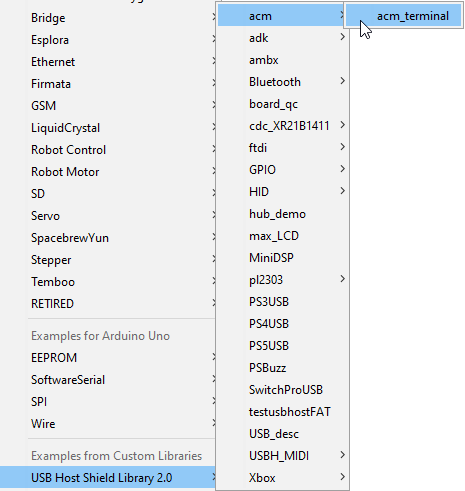
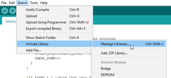
In Arduino IDE choose Sketch>Include Library>Manage Library
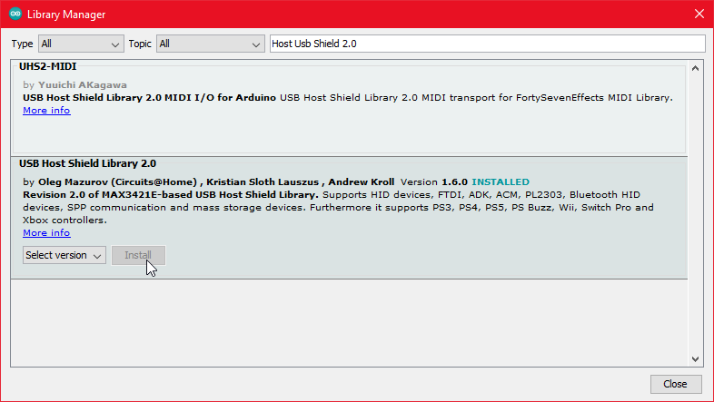
Search for USB Host Shield Library 2.0 and click ‘Install’
5. Running the example
In Arduino IDE click the upload button to upload the project to your Arduino.
Open up the ‘Arduino Uno Viritual COM Port’ with a serial terminal emulation program like TeraTerm, Putty or CoolTerm.Serial port Setup: Baudrate: 115200 Data Bits: 8 Parity: None Stop Bits: 1 Flow Control: None
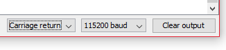
Or inside the Arduino IDE open up Arduino Monitor and in the bottom right corner select ‘Carriage Return’ and ‘115200 baud’
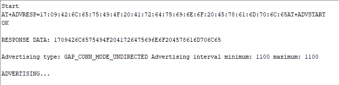
You should see the word ‘Start’ and then see the dongle running two commands: setting response data and starting the advertising. You can now type commands to the dongle.
The project is a simple example showcasing a quick way to set up a STM32Cube project as a USB CDC Host capable of communicating with the BleuIO Dongle.
When a BleuIO Dongle is connected to the Nucleo boards USB port the STM32 will recognize it. It will then accept 3 different inputs from the UART and send one of 3 preprogrammed commands to the BleuIO Dongle based on the input. The commands that are used in this example are:
ATI (Dongle Information)
AT+ADVSTART (Starts Advertising)
AT+ADVSTOP (Stops Advertising)
We have used a STM32 Nucleo-144 development board with STM32H743ZI MCU (STM32H743ZI micro mbed-Enabled Development Nucleo-144 series ARM® Cortex®-M7 MCU 32-Bit Embedded Evaluation Board) for this example.
If you want to use another setup you will have to make sure it support USB Host and beware that the GPIO setup might be different and may need to be reconfigured in the .ioc file.
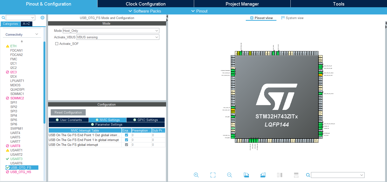
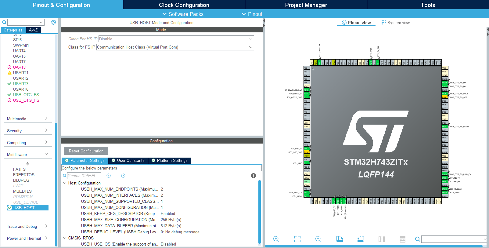
This project based on a new STM32 project with these changes in the .ioc file:
Under ‘Connectivity’ the ‘USB_OTG_FS’-mode is changed to Host_Only and in the NVIC Settings all global interrupts are enabled.
And under ‘Middleware’ the ‘USB_HOST’- ‘Class for FS IP’ is set to ‘Communication Host Class (Virtual Port Com)’.
To make sure the host would recognize when the bootloader is done and the BleuIO firmware is running this was added in the USBH_UserProcess function in ‘usb_host.c’ (found under ‘USB_HOST’ -> ‘App’ folder):
static void USBH_UserProcess (USBH_HandleTypeDef *phost, uint8_t id)
{
/* USER CODE BEGIN CALL_BACK_1 */
switch(id)
{
case HOST_USER_SELECT_CONFIGURATION:
break;
case HOST_USER_DISCONNECTION:
Appli_state = APPLICATION_DISCONNECT;
isBleuIOReady = false;
// Turn on Red LED, turn off Green and Yellow LED
HAL_GPIO_WritePin(GPIOB, GPIO_PIN_0, GPIO_PIN_RESET);
HAL_GPIO_WritePin(GPIOE, GPIO_PIN_1, GPIO_PIN_RESET);
HAL_GPIO_WritePin(GPIOB, GPIO_PIN_14, GPIO_PIN_SET);
break;
case HOST_USER_CLASS_ACTIVE:
Appli_state = APPLICATION_READY;
// Check if BleuIO firmware is running// (idProduct:0x6001 = bootloader, idProduct:0x6002 = bleuio fw)
if(phost->device.DevDesc.idProduct == 0x6002)
{
isBleuIOReady = true;
// Sends message to uart that BleuIO is connected and ready
HAL_UART_Transmit(&huart3, (uint8_t*)BLEUIO_READY, strlen(BLEUIO_READY), HAL_MAX_DELAY);
// Turn on Green LED, turn off Yellow and Red LED
HAL_GPIO_WritePin(GPIOB, GPIO_PIN_0, GPIO_PIN_SET);
HAL_GPIO_WritePin(GPIOE, GPIO_PIN_1, GPIO_PIN_RESET);
HAL_GPIO_WritePin(GPIOB, GPIO_PIN_14, GPIO_PIN_RESET);
// Start receiving from usb
USBH_CDC_Receive(&hUsbHostFS, CDC_RX_Buffer, RX_BUFF_SIZE);
}
break;
case HOST_USER_CONNECTION:
Appli_state = APPLICATION_START;
isBleuIOReady = false;
// Turn on Yellow LED, turn off Green and Red LED
HAL_GPIO_WritePin(GPIOB, GPIO_PIN_0, GPIO_PIN_RESET);
HAL_GPIO_WritePin(GPIOE, GPIO_PIN_1, GPIO_PIN_SET);
HAL_GPIO_WritePin(GPIOB, GPIO_PIN_14, GPIO_PIN_RESET);
break;
default:
break;
}
/* USER CODE END CALL_BACK_1 */
}
The Green, Red and Yellow LEDs on the Nucleo board is also setup to change based on the connection status.
Red = Disconnnected. Yellow = Connecting. Green = Connected.
An external variable bool isBleuIOReady is also set so the status of the dongle is accessible from main.c.
Once the BleuIO dongle is confirmed to be connected the USBH_CDC_Receive function is run to start reciving data from the USB CDC.
The USBH_CDC_ReceiveCallback also needs to be implemented:
void USBH_CDC_ReceiveCallback(USBH_HandleTypeDef *phost)
{
    if(phost == &hUsbHostFS)
    {
        // Handles the data recived from the USB CDC host, here just printing it out to UART
        rx_size = USBH_CDC_GetLastReceivedDataSize(phost);
        HAL_UART_Transmit(&huart3, CDC_RX_Buffer, rx_size, HAL_MAX_DELAY);

        // Reset buffer and restart the callback function to receive more data
        memset(CDC_RX_Buffer,0,RX_BUFF_SIZE);
        USBH_CDC_Receive(phost, CDC_RX_Buffer, RX_BUFF_SIZE);
    }

    return;
}
In this example the recieved data is just echoed to the UART.
To send data to the Dongle the USBH_CDC_Transmit function is used. In this example UART input is used to send different commands.
For this purpose a wrapper function has been created that can be accessed from main.c:
/**
  * @brief Simple function that takes a string and transmit it to the dongle
  * @retval None
  */
void writeToDongle(uint8_t * cmd)
{
    USBH_CDC_Transmit(&hUsbHostFS, cmd, strlen((char *)cmd));
}
In main.c HAL_UART_RxCpltCallback is implemented to recieve input from Uart and a simple UART input handler:
The handleUartInput() handles the inputs 0, 1 and 2 and maps each to a certain Dongle commands. The handler is then put inside the main loop.
/* Infinite loop *//* USER CODE BEGIN WHILE */
while (1)
{
/* USER CODE END WHILE */
MX_USB_HOST_Process();
/* USER CODE BEGIN 3 */// Simple handler for uart input
handleUartInput(uartStatus);
}
/* USER CODE END 3 */
A board with a STM32 Microcontroller with a USB port. (A Nucleo-144 development board: NUCLEO-H743ZI2, was used developing this example. (https://www.st.com/en/evaluation-tools/nucleo-h743zi.html) To connect the dongle to the Nucleo board a “USB A to Micro USB B”-cable with a USB A female-to-female adapter can be used.)
Either clone the project, or download it as a zip file and unzip it, into your STM32CubeIDE workspace.
4.2 Importing as an Existing Project
From STM32CubeIDE choose File>Import…
Then choose General>Existing Projects into Workspace then click ‘Next >’
Make sure you’ve choosen your workspace in ‘Select root directory:’
You should see the project “stm32_bleuio_example”, check it and click ‘Finish’.
5. Running the example
In STMCubeIDE click the hammer icon to build the project.
Open up the ‘STMicroelectronics STLink Virtual COM Port’ with a serial terminal emulation program like TeraTerm, Putty or CoolTerm.Serial port Setup: Baudrate: 115200 Data Bits: 8 Parity: None Stop Bits: 1 Flow Control: None
In STMCubeIDE click the green play button to flash and run it on your board. The first time you click it the ‘Run Configuration’ window will appear. You can just leave it as is and click run.
Connect the BleuIO Dongle.
Wait until the message: “[BleuIO Dongle Ready]” is shown.
– Press 0 to get device information:
– Press 1 to start advertising:
– Press 2 to stop advertising:
BlueIO dongle responses will be printed out to Virtual COM Port.
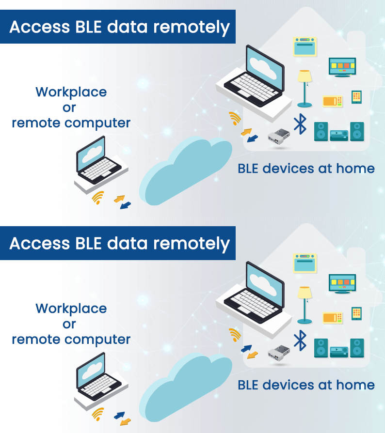
Suppose you have some BLE devices at your home and want to control or scan for those devices while at your workplace. In this project, we will discuss how to access BLE data remotely.
We have already created a script that communicates through BleuIO dongle remotely and gives us the response. You can access the script at
You are free to clone the script and make changes as you wish.
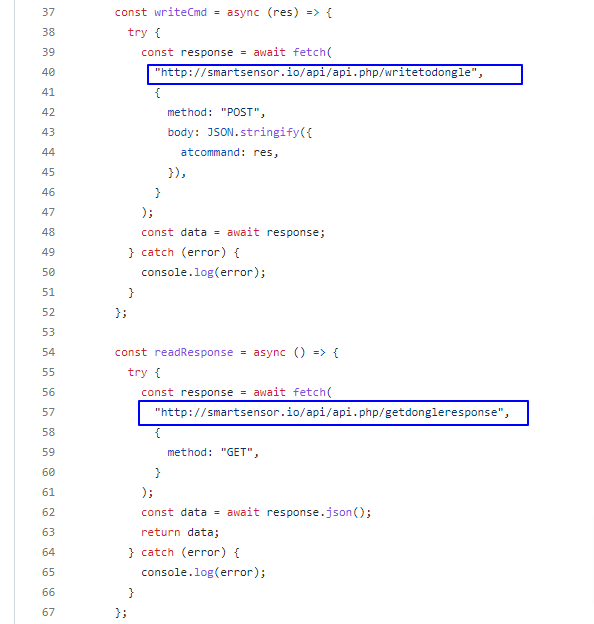
In this script, JavaScript is used to connect to the dongle using google chrome’s serial port. There is a simple PHP script that helps pass data through the cloud.
Step 1: Uploading
Upload the API folder in any server that supports PHP. This script reads and writes data to a JSON file upon request.
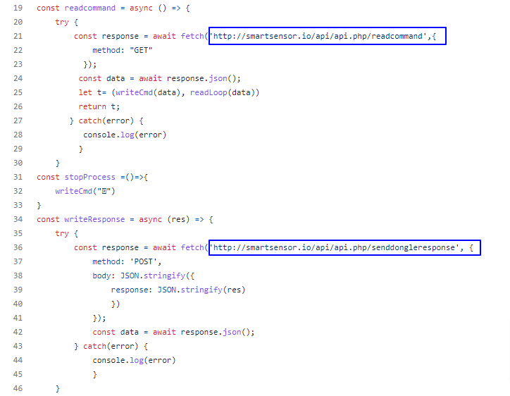
We have uploaded the file at http://smartsensor.io/api/api.php
You can use this URL if you don’t have a server to upload.
Step 2: Home computer setup
Open the index.js file found in the root folder and update the URL of the API file on both occasions.
You can leave the url as it is if you want to use file from our server.
Now connect a BleuIO dongle to your home computer and open the index.html file from the root folder.
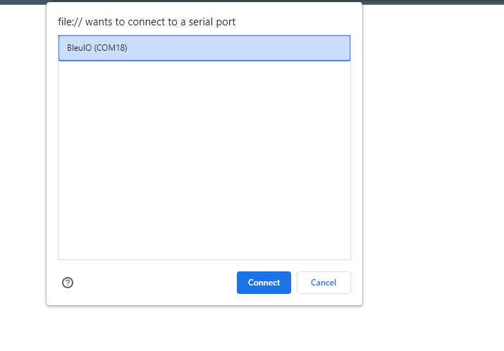
Click connect and select the COM port where the dongle is connected.
Open the index.html file found in the user folder and update the URL of the API file on both occasions.
You can leave the url as it is if you want to use file from our server.
Now open this file in a browser and start writing AT commands.
Currently, You can access the following AT commands
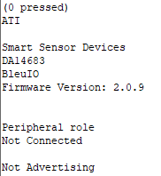
ATI ( Returns firmware version, hardware type and unique organization identifier, device connection status )
AT+CENTRAL (Sets the device Bluetooth role to central role.)
AT+PERIPHERAL (Sets the device Bluetooth role to the peripheral.)
AT+DUAL (Sets the device Bluetooth role to dual role. Which means it has both Central and Peripheral role capabilities.)
AT+ADVSTART (Starts advertising)
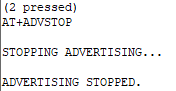
AT+ADVSTOP (Stops advertising. Returns ERROR if not already advertising)
AT+GAPSTATUS (Reports the Bluetooth role)
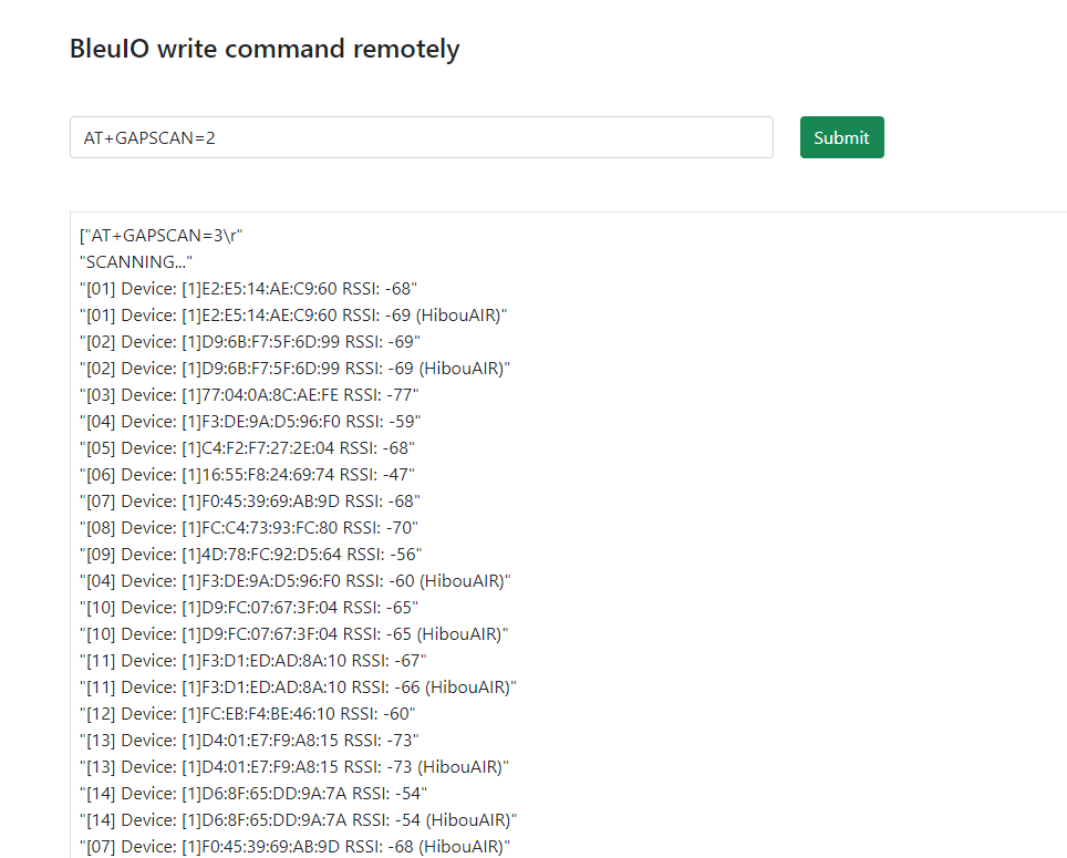
AT+GAPSCAN=2 (Starts a Bluetooth device scan with the timer set in seconds. Make sure to set a timer for the scan.)
Once you type one of the above commands, you will start to see the response from the dongle on your browser screen.
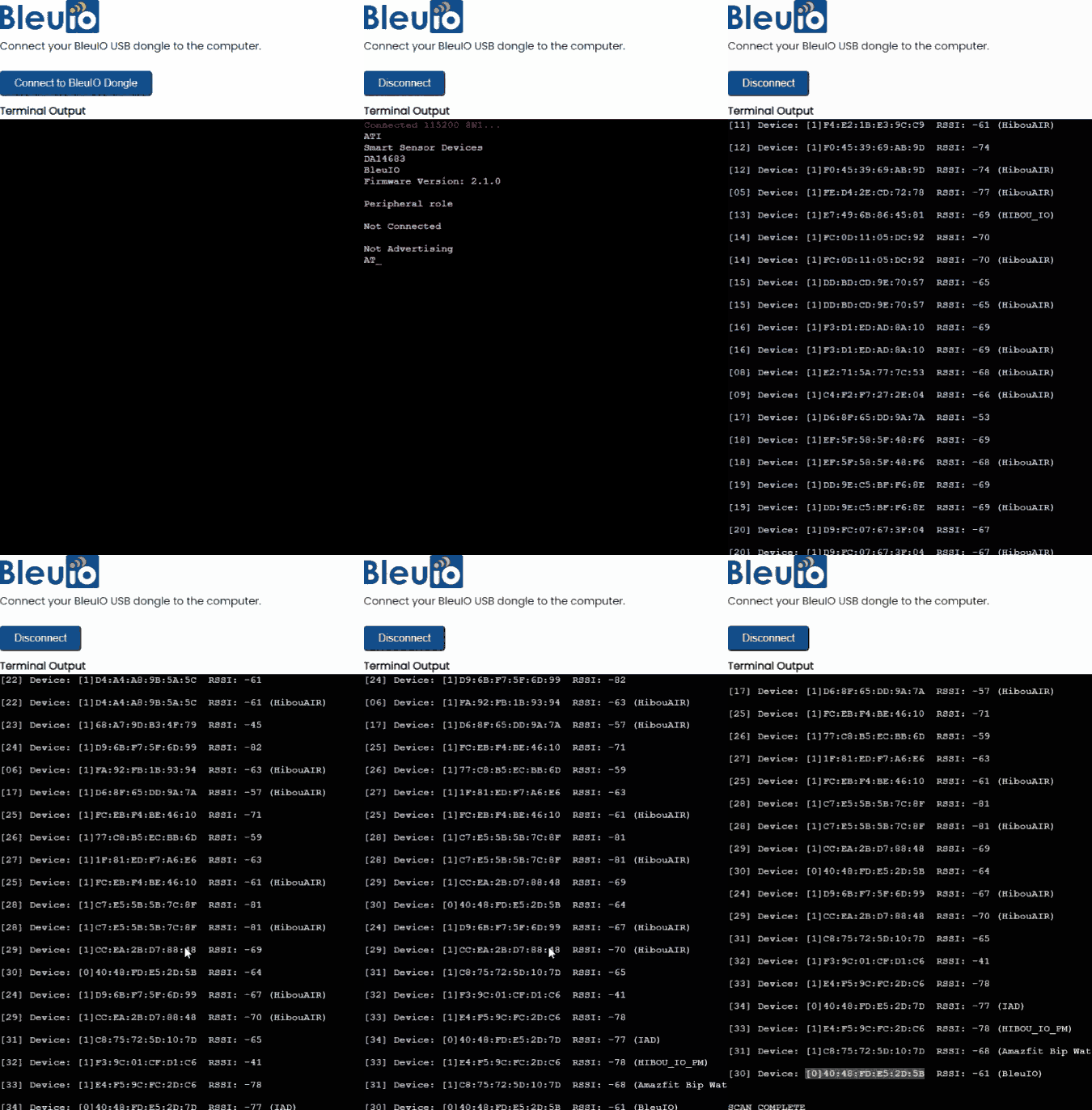
I am trying to scan for BLE devices at my home where BleuIO dongle is connected. Here I got a list of devices showing on my browser screen. Make sure the device is on central mode to scan for devices.
You can add more AT commands to the script as required. All you need to do is update the index.js file found in the root folder.
Find the list of AT commands our from getting started guide at