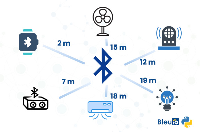
Bluetooth Advertisements are crucial for any BLE device since they are utilized for all types of applications, whether that’s a device that allows connections or one that simply advertises its presence and includes data for others to discover.
The most important goal of advertising packets is to convey information to other BLE devices via the advertising packet type, and the advertising data types included in the packet.
Bluetooth beacons are the most prominent devices that take full advantage of Bluetooth advertising packets. This is due to the reason that most beacons stay in the advertising state throughout their lifetime (do not allow connections), so they rely completely on advertising for relaying the relevant information to the scanning devices.
I tried to create a simple python example script that scans for nearby Bluetooth devices and returns the manufacturer company information by reading the advertising packet.
Requirments
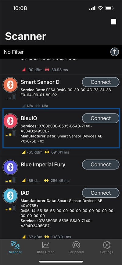
- Bluetooth Low Energy USB dongle BleuIO (https://www.bleuio.com)
- Pyserial.
Steps
- Get the script from GitHub at https://github.com/smart-sensor-devices-ab/python_bluetooth_device_info.git
- Connect the BleuIO to your computer. The script uses pyserial to connect to the Bluetooth USB dongle BleuIO.
- Update the script and write the correct COM port, where the dongle is connected. (main.py line 6)
- After connecting to the dongle, we put the dongle into the central role so that it can scan for nearby Bluetooth devices.
- Then we do a simple Gap scan using AT+GAPSCAN=3 command to scan for nearby Bluetooth devices for 3 seconds.
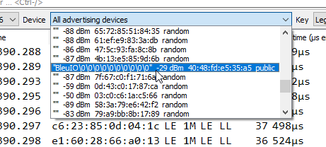
- After that, we read the output from the serial port and print out the list of devices with MAC addresses.
- User selects a device to get manufacturer company information
- We read the advertising packet for this specific device.
- Pass the response to a function which separates the manufacturer id.
- Then we try to find a match from an object which I have downloaded recently from https://www.bluetooth.com/specifications/assigned-numbers/company-identifiers/
- The company name shows on the screen.
Here is the final script file.
import serial
import time
from companydata import companyData


your_com_port = "COM18"  # Change this to the com port your dongle is connected to.
connecting_to_dongle = True

print("Connecting to dongle...")
# Trying to connect to dongle until connected. Make sure the port and baudrate is the same as your dongle.
# You can check in the device manager to see what port then right-click and choose properties then the Port Settings
# tab to see the other settings

# function to get company name from advertised id
def getCompany(adv):
  # example advertised package would look like this
  # 0201061BFF5B070504220118A3003127ED006901090100000000000001BD03
  # explains here
  # https://twitter.com/josryke/status/763006284052463617/photo/1
  indentifierReversed=''
  # first part 02 is the length
  length = int(adv[0:2],16)
  pl =int(adv[length*2+2:length*2+4 ], 16)
  # this gives us 1B which is 27 in decimal. that is our length
  startsFrom = length*2+4
  # this gives us 8, from where it starts
  # now get the packet
  fd=adv[startsFrom:pl]
  # look for the position of flag FF
  flagPosition = fd.find("FF")
  if flagPosition!=-1:
    identifier = fd[flagPosition+2:flagPosition+6]
    # get 5B07
    indentifierReversed = identifier[2]+identifier[3]+identifier[0]+identifier[1]
    # get 075B
    # now look for the company name on the list
    for attr in companyData:
        if attr['Hexadecimal']=='0x'+indentifierReversed:
            theName=attr['Company']
  else:
    indentifierReversed='-'
    theName='Unknown'

  return theName

while connecting_to_dongle:
    try:
        console = serial.Serial(
            port=your_com_port,
            baudrate=115200,
            parity="N",
            stopbits=1,
            bytesize=8,
            timeout=0,
        )
        if console.is_open.__bool__():
            connecting_to_dongle = False
    except:
        print("Dongle not connected. Please reconnect Dongle.")
        time.sleep(5)

print("Connected to Dongle.")

#put the dongle in dual role, so we can scan for nearby device
console.write(str.encode("AT+CENTRAL"))
console.write("\r".encode())
print("Putting dongle in Central role.")
time.sleep(0.1)
# Scan for nearby devices for 3 seconds
console.write(str.encode("AT+GAPSCAN=3"))
console.write("\r".encode())
time.sleep(0.1)
print("Looking for nearby Bluetooth devices ...")
dongle_output2 = console.read(console.in_waiting)
time.sleep(3)
filtered = []
# Filter out unncecssary outputs and keep only the list of devices (also remove index)
for dev in dongle_output2.decode().splitlines():
    if len(dev)>20:
        filtered.append(dev)

# Get unique device by device id and add distance to each raw
seen = set()
out = []
for elem in filtered:
    prefix = elem.split(' ')[2]
    if prefix not in seen:
        seen.add(prefix)
        out.append(elem)

# sort list by closest device
# out.sort(key=lambda x:int(x.split()[3]),reverse=True)
print("Scan Completed! "+ str(len(out)) +" devices found.")
# print(out)
for i in range(0, len(out)):
    print (out[i])

getInput = input("Select device from the list to get company identifier information (ex.1): ")
deviceToScan = out[int(getInput)-1].split(" ")[2]
# clear output
console.flushInput()
console.flushOutput()
time.sleep(0.1)
# Scan for advertised data of the selected device for 4 seconds
console.write(str.encode("AT+SCANTARGET="+deviceToScan+"=4"))
console.write("\r".encode())
time.sleep(0.1)
print("Getting company identifier information ...")
dongle_output3 = console.read(console.in_waiting)
time.sleep(5)
resp = dongle_output3.decode().splitlines()
# get the adv data only
for d in resp:
    if('[ADV]' in d):
        companyName=getCompany(d.split(" ")[-1])
        break;
print(companyName)
time.sleep(0.1)
console.close()
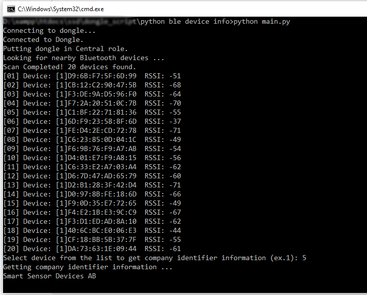
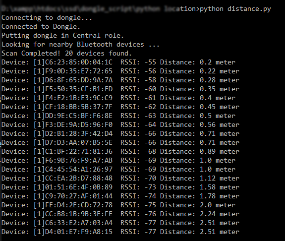
Output
After running the script, we see a total of 20 devices found nearby. The script prints out the manufacturer company information of the device [05] Device: [1]C1:BF:22:71:81:36