When it comes to creating Bluetooth Low Energy (BLE) applications, simplicity is key. That’s where BleuIO comes in – a handy USB dongle designed to make BLE development easier. With BleuIO, you can say goodbye to complicated programming because of its rich and user-friendly AT command interface. Instead of diving into complex programming languages, you can simply use AT commands to configure BleuIO as a central or peripheral device. This not only speeds up development but also makes BLE accessible to everyone, regardless of their programming background.
Autonomous Execution
One of BleuIO’s amazing features is its ability to execute commands automatically when it boots up. With the latest firmware updates, BleuIO can store up to 10 commands in its flash memory. So, when you power it up, it’ll jump into action, performing tasks like initializing as a beacon , setting specific characteristics and many more without needing a host computer.
Imagine the convenience of having BleuIO handle essential tasks on its own – it’s like having a trusty assistant for all your BLE needs!
Example of Auto Execution
BleuIO isn’t just limited to basic BLE functions – it can also emulate beacons with ease. With a simple command, you can turn BleuIO into a powerful beacon, broadcasting custom data effortlessly. Moreover, with its flash memory capabilities, your configurations persist through power cycles, eliminating the need for repeated setup. Additionally, you can easily set specific characteristics to tailor BleuIO’s behavior to your exact requirements.
To clear the auto execution commands type AT+CLRAUTOEXEC. BleuIO puts you in control, so you can focus on bringing your ideas to life.
Whether you’re a seasoned developer or a newbie, BleuIO is the best choice for your BLE applicaiton development with its user-friendly interface, autonomous execution capabilities, and versatility.
BleuIO, a pioneer in Bluetooth Low Energy (BLE) technology, is thrilled to introduce its latest firmware update, version 2.6.0. This release contains auto execution functionality, which enables users to automate tasks and execute commands effortlessly upon device startup.
Added Features:
Users can now configure up to 10 commands that will execute automatically upon the BleuIO device starting up. This commands are stored in the device’s flash memory, ensures that the commands persist even through power cycles, eliminating the need for manual intervention.
What truly sets this feature apart is its ability to function independently of a host computer. Unlike previous iterations where a host computer was necessary to trigger commands, BleuIO v2.6.0 allows AT COMMANDS execution directly from the device itself. Imagine the possibilities – from initiating beacon advertising to executing custom routines – all with the simple power cycle of the device, no additional hardware required.
The startup execution mechanism further enhances the user experience. Upon startup, BleuIO checks for configured commands in the auto execute (AUTOEXEC) list and proceeds to execute them in the specified order. This streamlined process not only accelerates development but also ensures consistent performance, enabling rapid deployment of BLE applications with minimal effort.
New AT Commands:
The AT+AUTOEXECcommand enables users to both set and display commands in the AUTOEXEC list. Setting auto execution commands is as simple as using the syntax AT+AUTOEXEC=<cmd>, providing developers with a straightforward means of configuring device behavior.
Additionally, the AT+CLRAUTOEXEC command facilitates the removal of all commands set in the AUTOEXEC list, allowing for easy modification and refinement of device functionality. This level of flexibility helps developers to iterate quickly, experiment freely, and ultimately create BLE applications.
How to Upgrade:
To take advantage of these enhancements, make sure to update your BleuIO dongle to firmware version 2.6.0. You can find the firmware update and detailed instructions on the official BleuIO website. Click here to know more about firmware updates.
By introducing persistent auto execution commands and enhancing command management capabilities, BleuIO continues to lead the way in innovation, providing developers with the tools they need to create exceptional BLE solutions.
We are thrilled to announce the latest firmware update for BleuIO, version 2.5.0. In this release, we’ve introduced exciting features and commands that significantly enhance the user experience.
Added Features:
Bonding Information Persistence:
The standout feature of this update is the persistence of bonding information across power cycles. Now, when you establish a bond with another device using either the AT+GAPPAIR=BOND command from the dongle or the corresponding command from the paired device, the bond will remain active even after unplugging the BleuIO dongle. This ensures a seamless reconnection experience, saving you time and effort.
To check the bonding status, simply run AT+GETCONN when connected. This command will indicate whether you are bonded or not. To remove bonding information, the AT+GAPUNPAIR command can be used. This command provides the flexibility to either remove all bonded device information or selectively remove the bonding information of a specific device using the AT+GAPUNPAIR=[addrType]MacAddress format.
New AT Command: AT+GETBOND
We have introduced a new AT command – AT+GETBOND. This command allows you to display the MAC addresses of all bonded devices, providing valuable insights into the devices currently paired with your BleuIO dongle. What’s more, you can run this command at any time, even when not connected, giving you the flexibility to manage your bonded devices effortlessly.
Bug Fixes:
Command AT+GETCONN Enhancement:
In this release, we’ve addressed a minor issue related to the AT+GETCONN command. We removed a verbose line that was displayed when the BleuIO dongle was not in verbose mode. This ensures a cleaner and more streamlined experience when using this command.
How to Upgrade:
To take advantage of these enhancements, make sure to update your BleuIO dongle to firmware version 2.5.0. You can find the firmware update and detailed instructions on the official BleuIO website. Click here to know more about firmware updates.
We are committed to continuously improving BleuIO and providing you with the latest features and capabilities.
Bluetooth Low Energy (BLE) is a powerful technology for connecting devices wirelessly, and developing applications for BLE devices can be both exciting and challenging. In this tutorial, we’ll explore how to create a simple BLE device scanner using Python, Flask, and the BleuIO USB dongle. The BleuIO dongle provides a convenient interface through AT commands, allowing developers to easily interact with BLE devices.
Prerequisites
Before we dive into the tutorial, make sure you have the following:
Let’s start by examining the Python Flask code provided in app.py. This code defines a Flask web application with two routes: the home route (/) and a route to run the BLE device scan (/run_scan). The app uses the serial library to communicate with the BleuIO dongle over the serial port.
from flask import Flask, render_template, request
import serial
import time

app = Flask(__name__)

def scan_ble_devices():
    connecting_to_dongle = 0
    print("Connecting to dongle...")

    while connecting_to_dongle == 0:
        try:
            console = serial.Serial(
                port='/dev/cu.usbmodem4048FDE52DAF1',
                baudrate=57600,
                parity="N",
                stopbits=1,
                bytesize=8,
                timeout=0
            )
            if console.is_open.__bool__():
                connecting_to_dongle = 1
        except:
            print("Dongle not connected. Please reconnect Dongle.")
            time.sleep(5)

    console.write(str.encode("AT+CENTRAL"))
    console.write('\r'.encode())
    time.sleep(0.1)
    console.write(str.encode("AT+GAPSCAN=2"))
    console.write('\r'.encode())
    time.sleep(3)
    json_responses = []

    while console.inWaiting() > 0:
        line = console.readline().decode().strip()
        print(line)
        if line.startswith('['):
            json_responses.append(line)

    console.close()
    return json_responses

@app.route('/')
def home():
    return render_template('index.html')

@app.route('/run_scan', methods=['POST'])
def run_scan():
    if request.method == 'POST':
        json_responses = scan_ble_devices()

        return render_template('index.html', json_responses=json_responses)

if __name__ == '__main__':
    app.run(debug=True,port=5001)
HTML Template (index.html)
The HTML template (index.html) defines a simple web page with a button to trigger the BLE device scan. The page displays the results of the scan in an unordered list. Make sure the index.html file should stay inside template folder. so the folder structure should be like this
├── app.py
└── templates
    └── index.html
Code for index.html is provided below
<!DOCTYPE html>
<html lang="en">
<head>
<meta charset="UTF-8" />
<meta name="viewport" content="width=device-width, initial-scale=1.0" />
<title>Flask BLE Device Scanner</title>
<link
href="//cdn.muicss.com/mui-0.10.3/css/mui.min.css"
rel="stylesheet"
type="text/css"
/>
</head>
<body>
<div class="mui-container">
<br /><br />
<div class="mui-panel">
<img
src="https://flask.palletsprojects.com/en/3.0.x/_images/flask-horizontal.png"
alt=""
height="100"
/>
<img
src="https://1000logos.net/wp-content/uploads/2020/08/Python-Logo.png"
alt=""
height="100"
/>
<h1>Hello, Python BLE programmer!</h1>
<p>
This is a simple web page created with Flask to interact with BLE
devices nearby.
</p>
<form action="/run_scan" method="post">
<button
type="submit"
class="mui-btn mui-btn--primary mui-btn--raised"
>
Scan for BLE Devices
</button>
</form>
<br />
{% if json_responses %}
<ul class="mui-list--unstyled">
{% for json_response in json_responses %}
<li style="margin-bottom: 10px">
✓ {{ json_response | safe }}
</li>
{% endfor %}
</ul>
{% endif %}
</div>
</div>
</body>
</html>
Explaining the Code
Let’s dive into the connection part of the code and explain how the serial port is specified and why it is essential.
In this code snippet, the serial.Serial function is used to create a serial port object (console) for communication with the BleuIO dongle. Let’s break down the parameters used in this function:
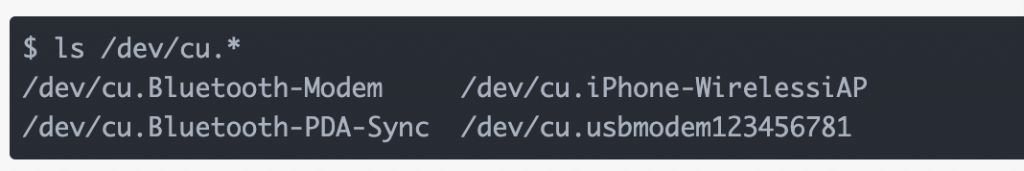
port: Specifies the name or address of the port to which the BleuIO dongle is connected. In this case, it is set to '/dev/cu.usbmodem4048FDE52DAF1'. On macOS, /dev/cu.* represents serial ports, and by running ls /dev/cu.* in the terminal, you can see a list of connected devices. The specific port for the BleuIO dongle is copied from this list and pasted into the code.
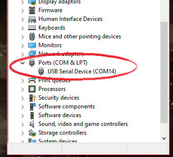
For windows the COM port information can be found here. Here the path for the dongle is COM14
baudrate: Sets the baud rate for communication. The BleuIO dongle communicates at a baud rate of 57600, so it is set accordingly.
parity: Specifies the parity checking scheme. In this case, it is set to “N” for no parity.
stopbits: Defines the number of stop bits. It is set to 1, which is a common configuration.
bytesize: Sets the number of data bits. It is set to 8, which is standard for most serial communication.
timeout: Sets the timeout for read operations. It is set to 0, meaning no timeout, allowing the code to wait indefinitely for responses from the BleuIO dongle.
It’s crucial to accurately specify the port to establish a successful connection between the Flask application and the BleuIO dongle. Incorrect port information will result in a failure to establish communication.
Connecting to BleuIO Dongle: The scan_ble_devices function attempts to establish a connection with the BleuIO dongle over the serial port. It retries until the connection is successful.
Sending AT Commands: The function sends specific AT commands to the dongle to set it in central mode (AT+CENTRAL) and initiate a BLE device scan for two seconds (AT+GAPSCAN=2).
Parsing JSON Responses: The function reads and parses the JSON responses received from the dongle. It collects the responses in a list (json_responses).
Flask Routes: The Flask app has two routes – the home route (/) renders the index.html template, and the /run_scan route triggers the BLE device scan and displays the results
To run the script simply run the following code on the terminal.
python app.py
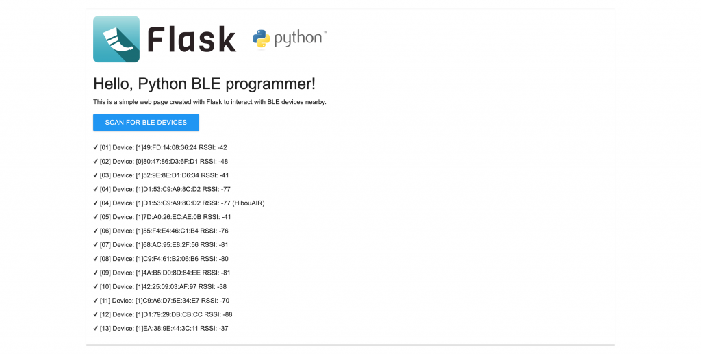
Output
In this tutorial, we’ve explored how to create a simple BLE device scanner using Python, Flask, and the BleuIO USB dongle. The combination of Flask and BleuIO’s AT commands provides a straightforward way for Python developers to interact with BLE devices, making BLE application development more accessible and efficient. You can further extend this project by adding features like connecting to specific BLE devices, reading characteristics, or even controlling devices. Details of the AT commands available on the BleuIO documentation.
To get started, make sure to have your BleuIO dongle, install Flask, and run the provided Python script. Happy BLE programming!
Bluetooth Low Energy (BLE) technology has become increasingly popular for creating wireless applications with low power consumption. In this tutorial, we’ll explore the process of scanning for nearby BLE devices, connecting to a specific device, and reading characteristics using the BleuIO BLE USB dongle. The tutorial is designed for Linux/MacOS environments.
Introduction to BleuIO
BleuIO is a versatile Bluetooth Low Energy USB dongle that simplifies BLE application development. It supports the AT command set, allowing developers to interact with the dongle using familiar commands. Whether you’re a seasoned BLE developer or just getting started, BleuIO offers a convenient and efficient way to work with BLE applications.
Forget complex libraries and complicated programming. Develop BLE applications effortlessly through simple AT commands.
Setting Up the Development Environment
Before diving into the tutorial, ensure you have the following prerequisites:
Python: Ensure that Python is installed on your system.
Writing the BLE Application Script
The provided Python script demonstrates the process of connecting to the BleuIO dongle, scanning for nearby BLE devices, and reading characteristics. Let’s break down the key components of the script:
# Importing necessary modules
import serial
import time

# Establishing connection to the BleuIO dongle
connecting_to_dongle = 0
print("Connecting to dongle...")

while connecting_to_dongle == 0:
    try:
        # Configuring the serial connection
        console = serial.Serial(
            port='/dev/cu.usbmodem4048FDE52CF21',
            baudrate=57600,
            parity="N",
            stopbits=1,
            bytesize=8,
            timeout=0
        )
        if console.is_open.__bool__():
            connecting_to_dongle = 1
    except:
        print("Dongle not connected. Please reconnect Dongle.")
        time.sleep(5)

# Sending commands to the BleuIO dongle
console.write(str.encode("AT+CENTRAL"))
console.write('\r'.encode())
time.sleep(0.1)
console.write(str.encode("AT+GAPSCAN=3"))
console.write('\r'.encode())
time.sleep(3.5)
console.write(str.encode("AT+GAPCONNECT=[1]D1:79:29:DB:CB:CC"))
console.write('\r'.encode())
console.write(str.encode("AT+GATTCREAD=0013"))
console.write('\r'.encode())

# Waiting for the dongle to respond
time.sleep(1)
out = ""
while console.inWaiting() > 0:
    out += console.read(console.inWaiting()).decode()
else:
    if not out.isspace():
        print(out + " ")
        out = " "
Explanation:
1. Connecting to BleuIO:
Download and install a serial terminal emulator like screen or minicom.
Ensure your dongle is connected and note its port (e.g., /dev/cu.usbmodem4048FDE52CF21).
Run the script with the correct port and baudrate (57600) in your terminal.
The script attempts connection until successful, then sends essential AT commands:
AT+CENTRAL: Configures BleuIO as a central device (scanning/connecting).
AT+GAPSCAN=3: Starts scanning for BLE devices for 3 seconds.
2. Selecting and Connecting:
The scan results will appear in your terminal.
Identify the desired device, usually by name or MAC address.
Replace D1:79:29:DB:CB:CC in the script with your device’s MAC address.
Send AT+GAPCONNECT=[1]D1:79:29:DB:CB:CC to connect to the device (replace the mac address with your desired device if needed).
3. Reading a Characteristic:
Every BLE device exposes characteristics containing specific data.
Replace 0013 in AT+GATTCREAD with the characteristic’s UUID to read its value.
This script reads the characteristic with UUID 0013 and prints its value. Currently its showing the device type.
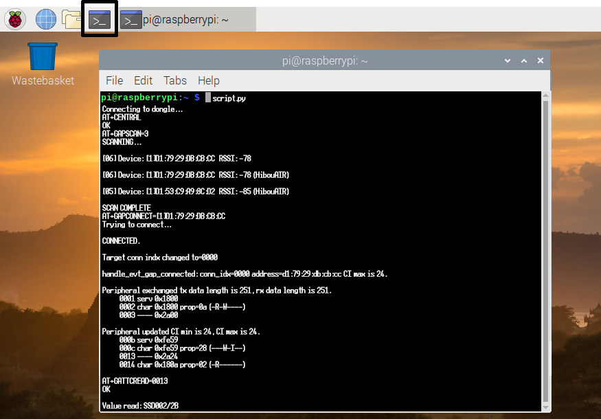
The outout
The output will be shown on the screen as
Value read: SSD002/2B
Hex: 0x5353443030322F3242
Size: 9
Understanding the Code:
The script uses serial library to communicate with BleuIO via AT commands.
While loops ensure connection success and read all available data.
The script parses output and filters empty space to avoid repetitive printing.
In this tutorial, we’ve covered the basics of working with the BleuIO BLE USB dongle on Linux/MacOS systems. The simplicity of the AT command interface and cross-platform compatibility make BleuIO an excellent choice for BLE application development. Experiment with the provided script, explore additional AT commands from BleuIO, and unlock the full potential of BLE applications with BleuIO. Happy coding!
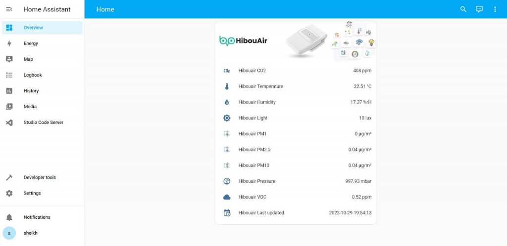
In this tutorial, we will walk you through the process of creating a Home Assistant integration to read air quality data from a BLE air quality monitor called HibouAir. To accomplish this, we’ll be using BleuIO, a BLE USB dongle, to read data via the serial port. BleuIO comes equipped with a Python library that simplifies the project significantly. This integration provides real-time updates of various air quality parameters, such as pressure, temperature, humidity, VOC, CO2 and Particle Matters.
Prerequisites
Before we dive into the implementation, make sure you have the following prerequisites in place:
HibouAir Air Quality Monitor: Ensure you have a HibouAir air quality monitor. You can obtain it from the official source.
BleuIO BLE USB Dongle: Acquire a BleuIO BLE USB dongle to facilitate communication with the HibouAir monitor.
Host Computer: We’ll use a Windows-based host computer in this example.
Home Assistant: Install Home Assistant and have it up and running. You can run Home Assistant within a virtual machine using VirtualBox, as demonstrated in this tutorial.
Implementation
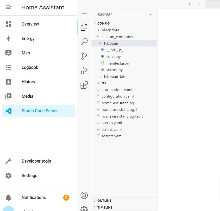
Let’s start by setting up the Home Assistant integration for HibouAir and BleuIO. You can find the complete code for this project on the following GitHub repository:
platform: Specifies the integration to use, which is hibouair_ble in this case.
scan_interval: Sets the interval for scanning and updating data. The example uses 120 seconds (2 minutes) for real-time data updates. Adjust this value according to your preference.
3. Restart Home Assistant
After updating the configuration, save the file and restart your Home Assistant instance. This will enable the integration.
4. Monitor Air Quality Data
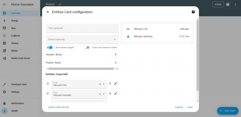
Once Home Assistant is restarted, you should be able to see entities representing various air quality parameters with the hibouair_ble prefix. These parameters may include pressure, temperature, humidity, VOC, CO2, and more. The air quality data will update every 2 minutes, providing real-time information about your environment.
After setting up the dashboard with the Hibouair_ble entities , the dashboard looks like this
This integration is a simple example, and you can further customize and automate your smart home based on the data collected from the HibouAir monitor. Feel free to adapt the code to your specific requirements and enhance the capabilities of your Home Assistant setup.
With the combination of HibouAir and BleuIO, you can effortlessly create a home automation system that ensures your environment remains healthy and comfortable.
Bluetooth Low Energy (BLE) is a wireless communication technology commonly used in various IoT and wearable devices. With the right tools and libraries, working with BLE devices on Linux becomes easy and efficient. In this tutorial, we’ll explore how to use the BleuIO dongle and the associated Python library to scan for nearby BLE devices, connect to a device, and read its characteristics, specifically the device name.
Prerequisites
Before we begin, ensure you have the following:
BleuIO Dongle: You’ll need a BleuIO dongle, a versatile BLE device capable of working on any platform.
BleuIO Python Library: Install the BleuIO Python library, which provides the necessary tools for interacting with the BleuIO dongle. You can install it using pip:
pip install bleuio
Now that you have the prerequisites in place, let’s dive into the process.
Step 1: Setting up the Python Script
First, let’s set up a Python script to work with the BleuIO dongle. Here’s a script that demonstrates how to scan for nearby BLE devices, connect to one of them, and read characteristics.
import time
from datetime import datetime
from bleuio_lib.bleuio_funcs import BleuIO

# Creating a callback function for scan results
def my_scan_callback(scan_input):
    print("\n\nmy_scan_callback: " + str(scan_input))

# Creating a callback function for events
def my_evt_callback(evt_input):
    cbTime = datetime.now()
    currentTime = cbTime.strftime("%H:%M:%S")
    print("\n\n[" + str(currentTime) + "] my_evt_callback: " + str(evt_input))

# Initiating the BleuIO dongle
my_dongle = BleuIO()

# Registering the callback functions
my_dongle.register_evt_cb(my_evt_callback)
my_dongle.register_scan_cb(my_scan_callback)

# Switch to Central or Dual Gap Role
my_dongle.at_dual()

# Start scanning for devices
my_dongle.at_gapscan(3)

# Wait for a few seconds to allow devices to be discovered
time.sleep(4)

# Connect to a device using its MAC address
my_dongle.at_gapconnect('[1]D1:79:29:DB:CB:CC')

# Wait for the connection to establish
time.sleep(4)

# Read characteristics with handle '0003', which contains the device name
my_dongle.at_gattcread('0003')

# Wait briefly
time.sleep(1)
Step 2: Running the Script
Save the script to a Python file, for example, bleuio_ble_tutorial.py. Then, run the script using your Python interpreter.
The script performs the following actions:
Initiates the BleuIO dongle and sets up callback functions for scan results and events.
Switches to Central or Dual Gap Role.
Scans for nearby BLE devices for a specified duration (3 seconds in this example).
Connects to a specific device using its MAC address.
Waits for the connection to establish.
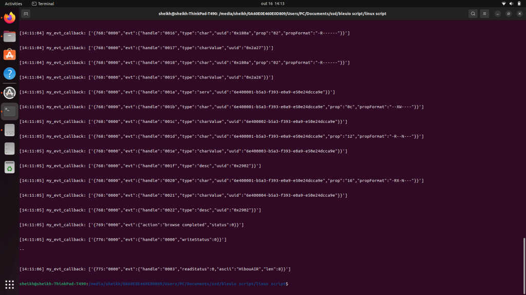
Reads the characteristics with handle ‘0003’, which typically contains the device name.
Waits briefly before exiting.
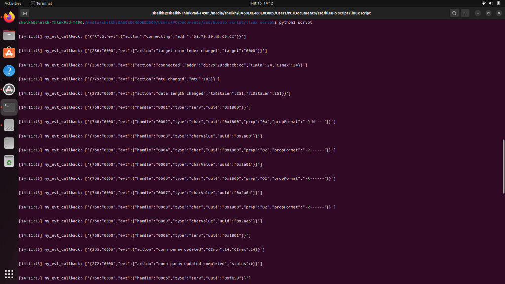
The scan results and characteristic data will be displayed on the terminal.
Output :
Working with BLE devices on Linux using the BleuIO dongle and Python library is a straightforward process. You can use this script as a starting point to interact with BLE devices and further develop your BLE applications. Remember to customize the script to suit your specific needs, and explore the wealth of possibilities that BLE technology offers in the world of IoT and wireless communication.
BleuIO, has recently unveiled its latest offering: Python Library v1.3.1. This release brings a range of improvements and features, including support for the SUOTA (Software Updates Over The Air) commands introduced in BleuIO firmware version 2.4.0. Additionally, it addresses a bug that affected MacOS users, making the library more robust and user-friendly.
Support for SUOTA Commands:
One of the standout features of BleuIO’s Python Library v1.3.1 is its support for SUOTA commands. SUOTA, which stands for Software Updates Over The Air, is a critical feature for any BLE device. It allows users to update firmware wirelessly, eliminating the need for physical connections or manual updates. With this library update, developers working with BleuIO now have a powerful tool at their disposal to streamline firmware updates for their BLE devices. Whether it’s fixing bugs or adding new features, the ability to update firmware over the air provides flexibility and convenience, ultimately enhancing the user experience.
Bug Fix for MacOS Users:
The new Python library also includes a significant bug fix for MacOS users. Previously, there was an issue where serial responses were sometimes returned in two parts instead of one when using the library on MacOS. This inconsistency could lead to compatibility problems and hinder the development process. BleuIO has promptly addressed this issue, ensuring that the library can now handle serial responses that come in multiple parts. This improvement guarantees a smoother experience for MacOS users and eliminates a common frustration during development.
The Python Library v1.3.1 by BleuIO is readily available for developers on the Python Package Index (PyPI). You can access and download the library from the following link: BleuIO Python Library on PyPI. This convenient accessibility ensures that developers can easily integrate the library into their projects and start benefiting from the new features and bug fixes immediately.
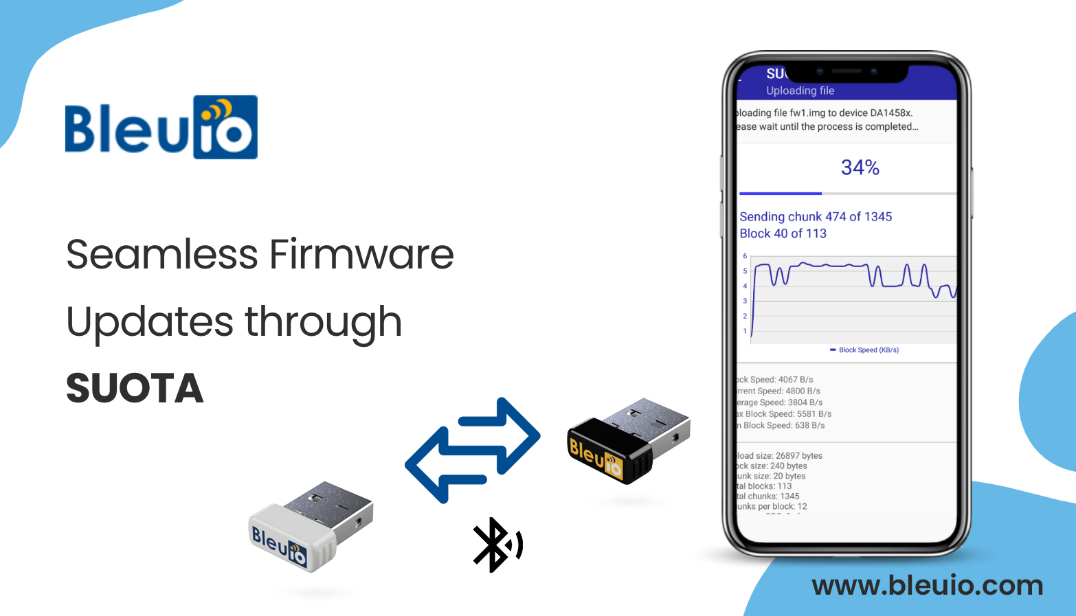
In today’s fast-paced world of technology, keeping devices up-to-date with the latest firmware is crucial for ensuring optimal performance, security, and functionality. To meet this demand, BLE (Bluetooth Low Energy) devices have become increasingly popular in various applications, from fitness trackers to smart home gadgets. One critical aspect of maintaining these devices is the ability to perform firmware updates seamlessly. BleuIO, a cutting-edge Bluetooth Low Energy USB dongle, has stepped up to the plate by offering support for SUOTA (Software Updates Over The Air), revolutionizing the way we update our Bluetooth-enabled devices.
Firmware updates are like lifelines for electronic devices. They bring enhancements, bug fixes, improved security, and often introduce new features to your gadgets. Without regular updates, devices can become vulnerable to security threats, suffer from performance issues, and lag behind in terms of functionality.
BleuIO is a highly versatile Bluetooth module that provides a wide range of capabilities, from supporting various Bluetooth profiles to enabling seamless communication between devices. One of the standout features of BleuIO is its support for SUOTA, which allows for effortless and efficient firmware updates. To avail this feature, ensure you update your BleuIO dongle to firmware version 2.4.0.
SUOTA, or Software Updates Over The Air, is a game-changer in the world of firmware updates. Unlike traditional methods that require a physical connection or specialized tools, SUOTA leverages Bluetooth technology to transmit firmware updates wirelessly. BleuIO’s integration of SUOTA support makes it a standout choice for developers and manufacturers looking to streamline firmware updates for their Bluetooth-enabled devices.
In a world where technology evolves rapidly, the ability to keep devices up-to-date is paramount. BleuIO’s support for SUOTA represents a significant leap forward in the realm of firmware updates. It offers convenience, cost-efficiency, speed, and security, all while enhancing the overall user experience. Whether you’re a developer or an end-user, BleuIO’s SUOTA support is a step in the right direction towards a smarter, more connected future.
BlueIO, a prominent player in the Bluetooth industry, has recently unveiled its firmware version v2.3.1. This update comes packed with exciting additions and crucial bug fixes, promising a more seamless and efficient Bluetooth experience.
Enhanced Features:
AT+SCANFILTER Upgrade: One of the standout features of the v2.3.1 firmware update is the enhancement made to the AT+SCANFILTER functionality. Previously, this feature only filtered based on UUID, but now, it has been extended to include “Service Data – 128-bit UUID” and “Service Data – 16-bit UUID” packets. This means that when filtering devices, you can now fine-tune your criteria even further, ensuring that only the most relevant devices are detected. This added flexibility is a significant boon for developers and users alike, enabling a more tailored Bluetooth experience.
Critical Bug Fixes:
SPS Message Recognition: Before the v2.3.1 update, some users may have encountered a frustrating issue where the dongle failed to recognize SPS (Serial Port Service) messages correctly. This problem stemmed from the system incorrectly handling messages due to a different handle, resulting in an improper display format that did not align with previous firmware versions. However, with the diligent efforts of the BlueIO team, this bug has been decisively squashed. Now, SPS messages are correctly recognized and displayed in a consistent manner, eliminating the confusion and inconvenience experienced by users.
AT+GETCONN Bonded Device Display: Another critical bug addressed in this firmware update relates to the AT+GETCONN command. Previously, when users attempted to reconnect with previously bonded or paired devices, these devices would not show up as bonded or paired during the reconnection process. This inconsistency could lead to unnecessary complications and frustration for users. Thankfully, BlueIO has rectified this issue in v2.3.1. Now, when you reconnect with your trusted devices, they will correctly appear as bonded or paired, streamlining the reconnection process and ensuring a smoother user experience.
Be sure to update your BlueIO firmware to v2.3.1 to take full advantage of these improvements and enjoy a more hassle-free Bluetooth experience. Details of the update can be found at