BleuIO JavaScript library received a significant update to version 1.1.2, allows compatibility with BleuIO firmware v2.7.1. This update introduces several new commands, expanding the capabilities of BleuIO and helps developers to innovate further.
Here’s a breakdown of the key additions in version 1.1.2:
at_customservice(): This function allows developers to set or query Custom Services, with the ability to add up to 5 Characteristics. Custom Services play a vital role in tailoring BLE applications to specific use cases, and this addition enhances flexibility in service customization.
at_customservicestart() and at_customservicestop(): These functions enable the starting and stopping of Custom Services based on the settings configured using at_customservice(). This dynamic control over service activation facilitates seamless integration and management of BLE functionalities.
at_customservicereset(): In scenarios where resetting Custom Service settings becomes necessary, this function comes to the rescue. It halts the Custom Service and resets configurations set by at_customservice(), ensuring a clean slate for subsequent operations.
at_suotastart() and at_suotastop(): The addition of these functions facilitates over-the-air firmware updates (SUOTA) by enabling or disabling the SUOTA Service and associated advertising. This capability simplifies the process of updating BLE devices remotely, enhancing maintenance and scalability.
at_autoexec() and at_clrautoexec(): These functions provide control over automatic execution of commands upon BleuIO startup. Developers can set or clear up to 10 commands, optimizing device initialization and enhancing user experience.
at_connparam(): This function simplifies the management of connection parameters, allowing developers to set or display preferred values. Real-time updates during connection enable fine-tuning of parameters for optimal performance.
How to use: Updating to BleuIO JavaScript library 1.1.2 is a straightforward process. Use the following commands to use the lates BleuIO JavaScript library npm i bleuio
Documentation and Further Details: Comprehensive details, usage examples, and guidelines to use the new functionalities introduced in version 1.1.2 of the BleuIO JavaScript library is available at the official NPM page https://www.npmjs.com/package/bleuio
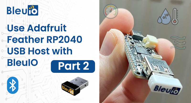
After following the steps in our previous post Integrating BleuIO with Adafruit Feather RP2040 for Seamless BLE Applications and trying out the Adafruit TinyUSB Library Example serial_host_bridge it is now time for a more practical example. This example is going to show you how to connect real sensors to the Feather, read the values and have it command the BleuIO to advertise them.
Basically you could say that you are going to create a autonomous BLE beacon that advertise the current temperature, humidity etc.
For this example we are using a Gas sensor BME680 and a OPT3002 Light-to-Digital Sensor.
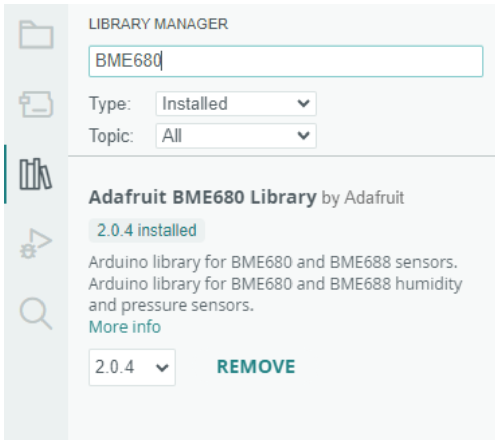
The libraries can easily be installed through the Arduino IDE:
Open Library Manager by clicking the Library Manager icon to the left or go through menu: Sketch>Include Libraries>Manage Libraries…
Search for Adafruit_BME680, and install the Adafruit_BME680 Library
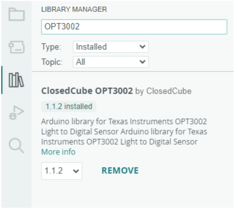
Search for ClosedCube OPT3002, and install the ClosedCube OPT3002 library
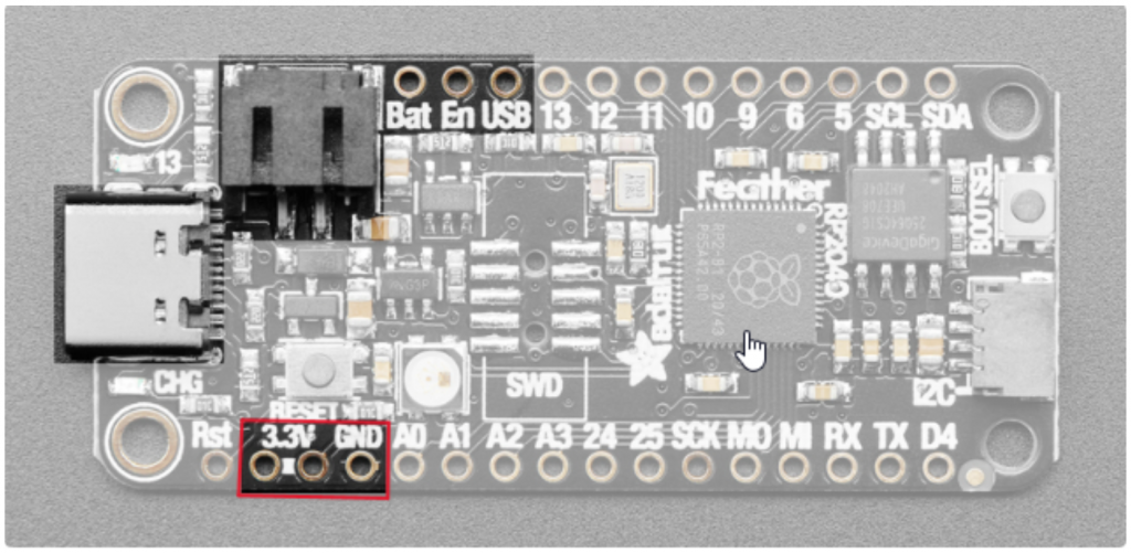
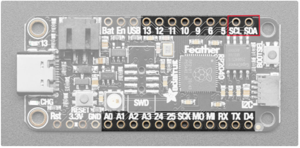
Connecting I2C sensors
Connect four wires (at a minimum) for each I2C device.
Power the device with 3.3V, then a ground wire.
And a SCL clock wire, and and a SDA data wire.
Running the example
Make sure the BleuIO Dongle is connected to the Feather RP2040 Board.
Connect the Feather RP2040 Board to your computer using the USB cable.
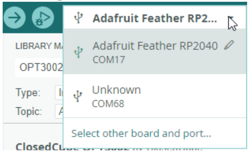
Make sure the Feather RP2040 Board is selected aswell as the correct COM port in the dropdown menu.
(Optional) Change the frequency the sensors are read and advertising data updated, in the code
// How often we read the sensors and update the advertings message
(in seconds)
#define READ_UPDATE_FREQUENCY   5
Click the Upload button.
Done! The dongle should now be advertising the sensor values. (If you just plugged in the Feather it may take about 10 seconds before advertising starts as the BleuIO bootloader opens and closes)
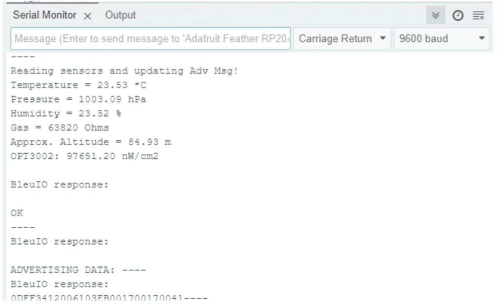
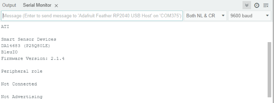
(Optional) Open Serial Monitor. You can open the Serial Monitor from the menu: Tools>Serial Monitor
You should now see the output from the project.
Scanning the results
To see the results you can use any BLE scanner app.
BleuIO Python library received a significant update to version 1.4.0, allows compatibility with BleuIO firmware v2.7.1. This update introduces several new commands, expanding the capabilities of BleuIO and helps developers to innovate further.
Enhanced Functionality: The latest BleuIO Python library update includes latest commands, aligning with the advancements in firmware v2.7.1. Let’s have a look into the key additions:
at_autoexec(): This command corresponds to AT+AUTOEXEC in the BleuIO firmware. It enables developers to configure automatic execution of specific actions upon device boot-up. Whether it’s initializing connections or setting parameters, at_autoexec() enables the initialization process, enhancing the efficiency of BLE applications.
at_clrautoexec(): This command corresponds to AT+CLRAUTOEXEC. It helps developers to clear the configured automatic execution settings on the BleuIO device. This function provides flexibility in modifying device behavior dynamically, ensuring seamless adaptability to changing project requirements.
at_connparam(): BLE connection parameters play a pivotal role in defining the characteristics of data transmission between devices. The addition of at_connparam() facilitates precise control over connection parameters, helps developers to optimize communication efficiency based on specific use cases.
at_getbond(): Security is paramount in BLE applications, especially concerning device bonding. The introduction of at_getbond() allows developers to retrieve bonding information from the BleuIO device, enabling seamless integration of security features and enhancing overall data integrity.
How to update: Updating to BleuIO Python library 1.4.0 is a straightforward process. Developers can leverage the command python -m pip install --upgrade bleuio to ensure they have access to the latest functionalities and optimizations.
Documentation and Further Details: Comprehensive details, usage examples, and guidelines to use the new functionalities introduced in version 1.4.0 of the BleuIO Python library is available at the official PyPI page https://pypi.org/project/bleuio/.
In today’s data-driven world, extracting meaningful insights from raw data is crucial for informed decision-making. Microsoft Excel stands as an amazing tool for data analysis, offering powerful features for visualization, manipulation, and interpretation. However, accessing and processing data from external sources, such as BLE devices, can often be challenging and time-consuming.
BleuIO revolutionizes BLE application development with its intuitive AT command interface, eliminating the need for complex coding. With BleuIO, developers can communicate effortlessly with BLE devices, retrieve data, and execute commands with ease. Whether you’re a seasoned developer or just starting out, BleuIO streamlines the development process, allowing you to focus on innovation rather than technical complications. In this tutorial we will see how to read data from an air quality monitoring BLE device and get it on Microsoft excel sheet for further analysis.
What is BleuIO?
BleuIO is a versatile BLE 5.0 USB dongle designed to simplify the development of BLE applications. With its AT command interface, developers can easily communicate with BLE devices without the need for complex coding. Whether you’re a beginner or an experienced developer, BleuIO makes BLE application development faster and more accessible.
Setting Up the Environment
Before we dive into the code, let’s set up our development environment. You’ll need:
To communicate with BleuIO, we’ll use Python and its serial library. First, ensure that you have the pyserial library installed. Then, connect BleuIO to your computer and identify the serial port it’s connected to. Next, we’ll send AT commands to BleuIO and retrieve the responses.
Here is the complete python code
import serial
import re
import json

# Define the serial port and baudrate
serial_port = "COM8"
baudrate = 57600


def read_response(ser):
    """
    Read response from serial port until a newline character is encountered.
    """
    response = b""
    while True:
        char = ser.read(1)
        if char == b"":
            break  # No more data to read
        response += char
        if char == b"\n\n":
            break  # Reached end of response
    return response.decode()


def hex_to_decimal(hex_str):
    """
    Convert hexadecimal string to decimal integer.
    """
    return round(int(hex_str, 16) / 10.0, 1)


def find_pattern(response):
    """
    Find and extract patterns matching the specified format.
    """
    pattern = r"\{T:\"(\w+)\",H:\"(\w+)\",PM1:\"(\w+)\"PM2\.5:\"(\w+)\"PM10:\"(\w+)\",IAQ:\"(\w+)\",PPM:\"(\w+)\"\}"
    matches = re.findall(pattern, response)
    return [
        {
            "T": hex_to_decimal(m[0]),
            "H": hex_to_decimal(m[1]),
            "PM1": hex_to_decimal(m[2]),
            "PM2.5": hex_to_decimal(m[3]),
            "PM10": hex_to_decimal(m[4]),
            # "IAQ": hex_to_decimal(m[5]),
            # "PPM": hex_to_decimal(m[6]),
        }
        for m in matches
    ]


def main():
    # Connect to the serial port
    ser = serial.Serial(serial_port, baudrate, timeout=1)

    # List to store responses
    responses = []

    # Send the command 'AT+CENTRAL' to the device
    ser.write(b"AT+CENTRAL\r")
    response = read_response(ser)

    # Connect to the device
    ser.write(b"AT+GAPCONNECT=[1]D1:53:C9:A9:8C:D2\r")
    response = read_response(ser)

    # Set notification
    ser.write(b"AT+SETNOTI=0021\r")
    response = read_response(ser)

    # Get all data
    ser.write(b"AT+GATTCWRITEWR=0021 GET DATA=ALL\r")
    while True:
        response = read_response(ser)
        responses.append(response.strip())
        if "DATA:END" in response:
            break  # End of response

    # Find and collect patterns matching the specified format
    collected_patterns = []
    for r in responses:
        pattern_matches = find_pattern(r)
        if pattern_matches:
            collected_patterns.extend(pattern_matches)

    # Convert to JSON
    json_data = json.dumps(collected_patterns, indent=2)
    print(json_data)

    # Close the serial port
    ser.close()


if __name__ == "__main__":
    main()
In this code we have
Establishes a connection to the serial port, sends commands to the BLE device, and retrieves responses of 7 days air quality data history stored in the device.
Parses the responses to extract relevant patterns using regular expressions.
Converts the extracted patterns into JSON format for easy handling and printing.
Finally, closes the serial port.
Integrating with Excel
Now, let’s integrate BleuIO with Excel to visualize and analyze the air quality data. By executing a Python script within Excel’s VBA environment, we can populate the data directly into Excel for further analysis.
Here is the complete code
Sub SerialCommunication()
    Dim response As String
    Dim pythonScriptPath As String
    Dim wsh As Object, exec As Object, output As String
    Dim jsonData As Object
    Dim obj As Object
    Dim i As Integer, j As Integer

    ' Set the path to the Python script
    pythonScriptPath = "C:\Users\PC\Desktop\excel bleuio\serial_communication.py" ' Update with the correct path

    ' Create Windows Script Host object
    Set wsh = CreateObject("WScript.Shell")

    ' Execute the Python script and capture its output
    Set exec = wsh.exec("python """ & pythonScriptPath & """")

    ' Read the output of the script
    output = exec.StdOut.ReadAll

    ' Parse JSON data
    Set jsonData = JsonConverter.ParseJson(output)

    ' Write headers in the first row
    i = 1 ' Starting row
    j = 1 ' Starting column
    For Each key In jsonData(1).Keys
        Sheet1.Cells(i, j).value = key
        j = j + 1
    Next key

    ' Write data into separate columns
    i = i + 1 ' Move to the next row
    For Each obj In jsonData
        j = 1 ' Starting column
        For Each key In obj.Keys
            Sheet1.Cells(i, j).value = obj(key)
            j = j + 1
        Next key
        i = i + 1 ' Move to the next row
    Next obj
End Sub
In this code we have,
Called the python script.
The response we got from python script we then passed it using JsonConverter.
Finally we loop through the object and presented it on the Excel sheet on their respective cells.
Set up JsonConverter
If you get error like JsonConverter object is not recognized, follow the steps:
Download JSONConverter.bas: You can download the JSONConverter.bas file from various sources online. Here is a good github link to download from. https://github.com/VBA-tools/VBA-JSON It’s a common utility module for VBA that provides JSON parsing capability.
Import JSONConverter.bas into your project: Open your Excel workbook, then go to the Visual Basic Editor (Alt + F11). From the menu, select File > Import File and choose the JSONConverter.bas file you downloaded. This will add the JSONConverter module to your project.
Ensure Microsoft Scripting Runtime Reference: Go to Tools > References in the VBA editor and ensure that “Microsoft Scripting Runtime” is checked. This is needed for dictionary objects used in JSON parsing.
Run the script
Insert a Button:
Go to the “Developer” tab in Excel. If you don’t see the “Developer” tab, you may need to enable it in Excel options.
Click on the “Insert” drop-down menu in the “Controls” group.
Choose the “Button” (Form Control) option.
Click and drag to draw the button on your worksheet.
Assign the Macro:
Right-click on the button you just inserted and select “Assign Macro”.
In the “Assign Macro” dialog box, you should see a list of available macros. Since you just created a new macro, it should be listed. In this case, it should be “SerialCommunication”.
Select the “SerialCommunication” macro and click “OK”.
Edit the Macro (if needed):
If you want to edit the macro, you can click on the “Edit” button in the “Assign Macro” dialog box. This will open the VBA editor where you can make changes to the macro.
Test the Button:
Click on the button you inserted in your worksheet. This should trigger the “SerialCommunication” macro, which will execute the VBA code to communicate with the serial port and display the response in Excel.
Ensure Correct Port and Settings:
Before testing, ensure that the COM port (COM8) and other settings in the VBA code match your requirements and device specifications.
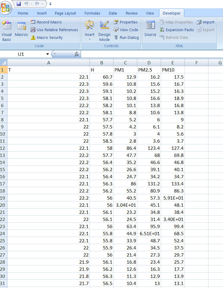
Output
Use Cases: Transforming Data into Actionable Insights
Indoor Air Quality Monitoring: Deploy BLE-enabled sensors in indoor environments to monitor air quality parameters such as temperature, humidity, and particulate matter. Excel’s data analysis capabilities enable users to identify trends, anomalies, and potential air quality issues, facilitating proactive measures for improving indoor air quality.
Environmental Studies and Research: Conduct environmental studies and research projects using BleuIO to collect air quality data in various outdoor settings. Excel serves as a powerful tool for data aggregation, statistical analysis, and visualization, enabling researchers to gain valuable insights into environmental patterns and trends.
Health and Safety Compliance: Ensure compliance with health and safety regulations by monitoring air quality in workplaces, public spaces, and industrial facilities. BleuIO, coupled with Excel, enables continuous monitoring of air quality parameters, facilitating compliance reporting and risk assessment processes.
By leveraging BleuIO’s seamless BLE communication capabilities and Excel’s robust data analysis features, developers and analysts can unlock the full potential of BLE application development and data analysis. Whether you’re monitoring air quality in indoor environments, conducting environmental research, or ensuring regulatory compliance, BleuIO and Excel provide a powerful combination for transforming raw data into actionable insights.
BleuIO, the versatile Bluetooth Low Energy (BLE) USB dongle renowned for simplifying BLE application development, has released a new firmware upgrade to version 2.7.0. This latest update brings forth new features and commands, further enables developers to create innovative BLE applications with ease.
Added Features:
Dynamic Connection Parameter Adjustment: One of the standout additions in firmware 2.7.0 is the ability to change connection parameters on the fly, even while maintaining a connection. This feature not only facilitates fine-tuning of BLE connections but also provides flexibility in adapting to varying network conditions. Additionally, developers can modify default connection parameters for improved efficiency when utilizing the AT+GAPCONNECT command with just the MAC address as an argument.
New Commands:
AT+CONNPARAM: This command emerges as a powerful tool for setting or displaying preferred connection parameters. When executed while connected, it enables seamless updating of connection parameters on the current target connection, streamlining the optimization process for BLE applications.
With these enhancements, BleuIO offers rapid BLE development solution. Whether you’re a seasoned developer or pro in BLE applications development, firmware 2.7.0 unlocks new possibilities and simplifies the path to crafting cutting-edge solutions.
How to Upgrade:
To take advantage of these enhancements, make sure to update your BleuIO dongle to firmware version 2.7.0. You can find the firmware update and detailed instructions on the official BleuIO website. Click here to know more about firmware updates.
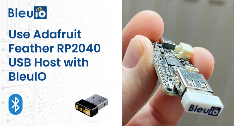
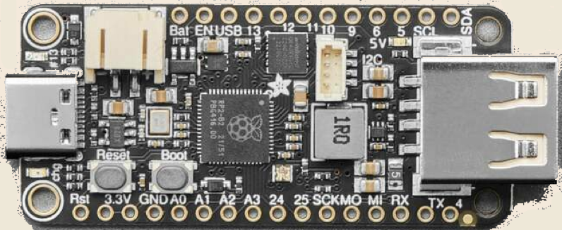
In the realm of IoT projects, finding a reliable and efficient host hardware solution is important. The Adafruit Feather RP2040 is an excellent solution for that. It comes equipped with a comprehensive ecosystem, including an IDE and libraries tailored for your new projects. With this setup, you get to keep the main USB port for uploading, debugging, and data communication, while at the same time sending and receiving data to just-about-any USB device, like the BleuIO.
In this first blog with the Adafruit Feather board, we are going to show how you can setup the USB stack and communicate with BleuIO using the Adafruit Feather RP2040 board. Later in next project we will show how to read a Temperature and Humidity sensor and display the data help of the Bluetooth Low Energy (BLE) interface.
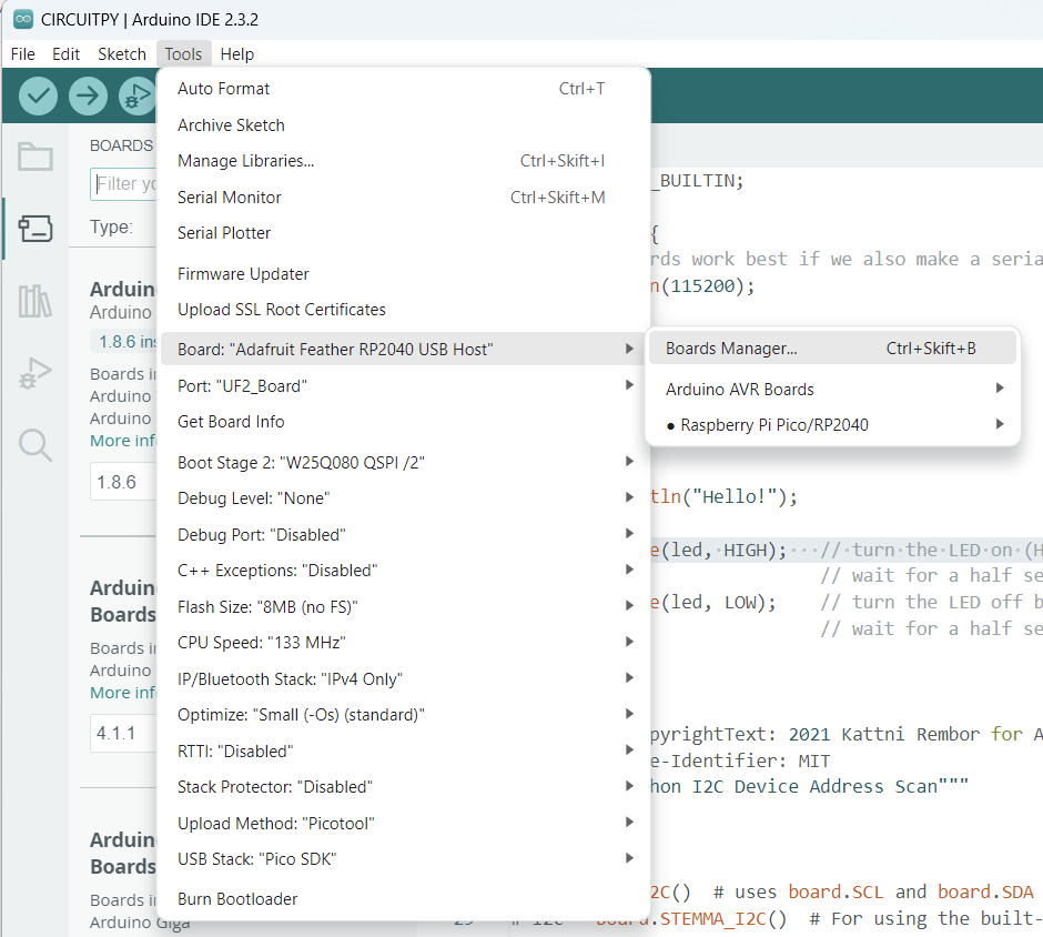
In the Arduino IDE, click on Tools > Board > Boards Manager. If you have previously selected a board, the Board menu item may have a board name after it.
In the Boards Manager, search for RP2040. Scroll down to the Raspberry Pi Pico/RP2040 by Earle F Philhower, III entry. Click Install to install it.
Choose Your Board
In the Tools > Boards menu, you should now see Raspberry Pi RP2040 Boards (possibly followed by a version number).
Navigate to the Raspberry Pi RP2040 Boards menu and choose Adafruit Feather RP2040 USB Host.
Now you’re ready to begin using Arduino with your RP2040 board! The main use case for this Feather is to act as a USB host.
Library Installation
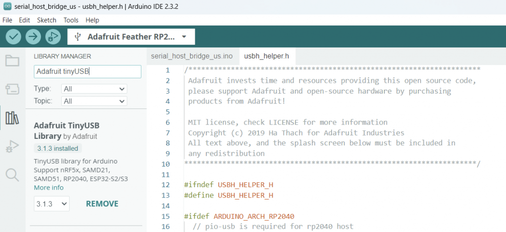
Install Adafruit_TinyUSB Library
To use your Feather as a USB host, you’ll need to install the Adafruit TinyUSB library. It can be installed using the Library Manager in the Arduino IDE.
Click the Manage Libraries > menu item, search for Adafruit TinyUSB, and select the Adafruit TinyUSBLibrary
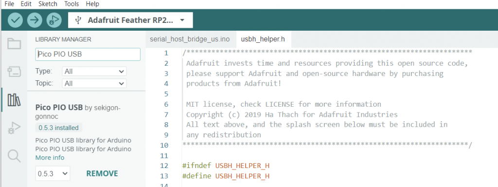
Install Pico PIO USB Library
Additionally, you’ll need to install the Pico PIO USB library.
Click the Manage Libraries > menu item again, search for PIO USB, and select the Pico PIO USB library.
Configuration and Deployment
Board Upload Settings
In the Tools menu, select Adafruit Feather RP2040 USB Host under Board.
For CPU Speed, you’ll need to select 120 MHz or240 MHz.
Finally, under USB Stack, select Adafruit TinyUSB.
Serial Host Bridge Example
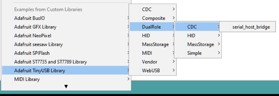
Load the example code onto your Feather after following the library installation instructions on the Arduino Library Install page.
Navigate to the Adafruit TinyUSB Library Examples and select DualRole – CDC – serial_host_bridge
Now you can control the BleuIO USB Dongle via the Adafruit Feather board.
With these steps completed, you’re now ready to start integrating BleuIO with your Adafruit Feather RP2040 board. This setup lays the foundation for exciting IoT projects, and we’ll explore more functionalities in future tutorials where we will show how to make the BleuIO USB Dongle advertise data from a Temperature and Humidity sensor.
Stay tuned for further guides on applying BleuIO and Adafruit Feather RP2040 for your projects!
In this tutorial, we will explore how to use BleuIO, a Bluetooth Low Energy (BLE) USB dongle, for developing BLE applications with C++. We’ll demonstrate how to connect to BleuIO via a serial port, send AT commands, and receive responses. Additionally, we’ll discuss the benefits of using BleuIO and provide some use cases for BLE application development with C++.
Introduction to BleuIO
BleuIO is a BLE USB dongle designed to simplify and accelerate the development of BLE applications. It provides a set of AT commands that allow developers to interact with BLE devices and services without having to write extensive code. By leveraging these AT commands, developers can quickly prototype and develop BLE applications with minimal effort.
Prerequisites
Before getting started, ensure you have the following:
Serial communication library for C++ (e.g., <iostream>, <unistd.h>, <fcntl.h>, <termios.h>)
Basic knowledge of C++ programming
Setting Up the Environment
First, connect the BleuIO dongle to your computer via USB. Then, (for MAC operating system) determine the serial port assigned to the dongle using the ls /dev/cu.* command in the terminal. Note down the serial port name (e.g., /dev/cu.usbmodem4048FDE52DAF1) as we’ll need it to establish a serial connection.
Writing the C++ Program
Below is a C++ program that connects to BleuIO, sends an AT command, and retrieves the response.
#include <iostream>
#include <string>
#include <unistd.h>
#include <fcntl.h>
#include <termios.h>
#include <chrono>
#include <thread>

int main() {
    // Open the serial port
    const char* portname = "/dev/cu.usbmodem4048FDE52DAF1"; // Change this to match your serial port
    int serial_port = open(portname, O_RDWR);
    if (serial_port < 0) {
        std::cerr << "Error opening serial port" << std::endl;
        return 1;
    }

    // Configure the serial port settings
    struct termios tty;
    tcgetattr(serial_port, &tty);
    cfsetospeed(&tty, B9600); // Set baud rate to 9600
    cfsetispeed(&tty, B9600);
    tty.c_cflag &= ~PARENB; // No parity
    tty.c_cflag &= ~CSTOPB; // 1 stop bit
    tty.c_cflag &= ~CSIZE;
    tty.c_cflag |= CS8; // 8 bits per byte
    tty.c_cflag &= ~CRTSCTS; // Disable hardware flow control
    tty.c_cflag |= CREAD | CLOCAL; // Enable reading and ignore control lines
    tty.c_lflag &= ~(ICANON | ECHO | ECHOE | ISIG); // Raw input

    tcsetattr(serial_port, TCSANOW, &tty);

    // Write data to the serial port to put the dongle in central role
    const char* m1 = "AT+CENTRAL\r";
    write(serial_port, m1, strlen(m1));

    // Wait for 1 second to receive the response
    std::this_thread::sleep_for(std::chrono::seconds(1));

    // Write data to the serial port to scan for nearby device for three seconds
    const char* m2 = "AT+GAPSCAN=3\r";
    write(serial_port, m2, strlen(m2));

    // Wait for 1 second to receive the response
    std::this_thread::sleep_for(std::chrono::seconds(1));

    // Read response from the serial port with timeout
    char buf[1024];
    std::string response;
    int nbytes;
    fd_set fds;
    struct timeval timeout;
    FD_ZERO(&fds);
    FD_SET(serial_port, &fds);
    timeout.tv_sec = 3; // Timeout after 3 second
    timeout.tv_usec = 0;
    while (select(serial_port + 1, &fds, NULL, NULL, &timeout) > 0) {
        nbytes = read(serial_port, buf, sizeof(buf));
        if (nbytes < 0) {
            std::cerr << "Error reading from serial port" << std::endl;
            close(serial_port);
            return 1;
        }
        if (nbytes > 0) {
            response.append(buf, nbytes);
        }
    }

    // Display the response
    std::cout << "Response: " << response << std::endl;

    // Close the serial port
    close(serial_port);

    return 0;
}
Understanding the Code
We start by opening the serial port corresponding to BleuIO.
Next, we configure the serial port settings (baud rate, parity, stop bits, etc.) to match BleuIO’s communication parameters.
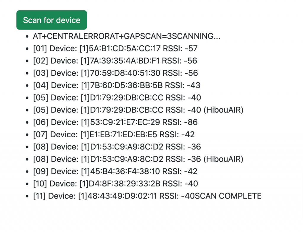
We then send the AT+CENTRAL command to BleuIO, which puts the dongle into central role.
After sending the command, we wait for 1 second to receive the response.
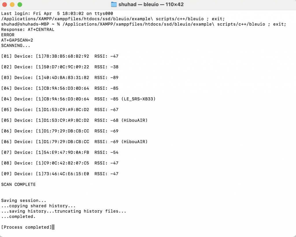
Then we send AT+GAPSCAN=3 to scan for nearby BLE devices for 3 seconds.
We read the response from the serial port with a timeout of 3 second.
Finally, we display the response received from BleuIO and close the serial port.
Output
Use Cases
BleuIO, with its AT command interface, presents an excellent starting point for developers looking to delve into Bluetooth Low Energy (BLE) application development with C++ across various domains.
Embedded Systems Development: BleuIO simplifies BLE application development in C++ for embedded systems. Developers can quickly prototype IoT devices, smart sensors, and wearables with BleuIO’s AT command interface, enabling features like remote control and wireless connectivity.
Cross-Platform Mobile Applications: Integrating BLE features into C++ mobile apps becomes seamless with BleuIO. Developers using frameworks like Qt or cross-platform tools can leverage BleuIO’s AT commands for device discovery, data exchange, and configuration across different platforms.
Industrial Automation and Control: C++ developers in industrial settings can enhance control systems and monitoring tools with BLE connectivity using BleuIO. Its AT command support enables communication with BLE-enabled equipment for tasks like remote monitoring and real-time data acquisition.
Educational Projects and Prototyping: BleuIO serves as an accessible platform for learning BLE technology with C++. Students and hobbyists can experiment with Bluetooth communication, protocol implementation, and IoT development, turning ideas into reality with minimal overhead.
In this tutorial, we’ve demonstrated how to use BleuIO for BLE application development with C++. By leveraging BleuIO’s AT commands, developers can streamline the development process and accelerate time-to-market for BLE-enabled projects. With the provided code and insights, you can now begin exploring BLE application development using BleuIO and C++ in your own projects.
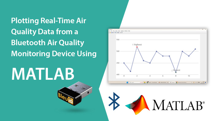
With the rise of IoT devices, Bluetooth Low Energy (BLE) technology has emerged as a convenient solution for wireless data transmission. In this tutorial, we’ll explore how to read real-time air quality data from a BLE air quality monitoring device called HibouAir, and plot it using MATLAB. To accomplish this, we’ll utilize the BleuIO BLE USB dongle, which simplifies BLE application development with its AT command interface.
Project Components:
BleuIO BLE USB Dongle: The BleuIO dongle serves as our BLE interface, allowing us to communicate with BLE devices using simple AT commands. Its plug-and-play nature and versatile features make it an ideal choice for BLE application development.
HibouAir Air Quality Monitoring Device: HibouAir is a BLE-enabled air quality monitoring device that measures various parameters such as CO2, temperature, humidity, VOCs, and more. It provides real-time data transmission via BLE, making it suitable for IoT applications.
MATLAB: MATLAB is a powerful computing environment widely used for data analysis, visualization, and algorithm development. We’ll leverage MATLAB’s capabilities to read data from the BleuIO dongle, decode BLE advertisements from HibouAir, and plot the air quality data in real-time.
Project Implementation:
Step 1: Setting up the Hardware
Connect the BleuIO BLE USB dongle to your computer’s USB port.
Power on the HibouAir air quality monitoring device.
Step 2: Writing MATLAB Code
Define the serial port parameters in MATLAB to establish communication with the BleuIO dongle.
Scan for a specific HibouAir device with its MAC address to get air quality advertised data.
Implement functions to decode BLE advertisement data from HibouAir, including parsing CO2, temperature, humidity, and other relevant parameters.
Write code to continuously scan for BLE advertisements, extract air quality data, and plot co2 value real-time using MATLAB’s plotting functions.
How This Project Can Be Helpful for Engineers, Developers, and Analysts
Environmental Monitoring: Engineers and analysts can use this project to create efficient environmental monitoring systems. By integrating BLE air quality monitors with MATLAB’s data analysis tools, they can assess air quality, detect anomalies, and optimize environmental control systems.
Use Case: A civil engineering firm employs this setup to monitor indoor air quality in commercial buildings, identifying areas needing ventilation improvements.
IoT Development: Developers can leverage this project to build IoT applications across various industries. By connecting BLE monitors with cloud platforms and mobile apps, they enable remote monitoring and predictive maintenance.
Use Case: A startup develops a mobile app for real-time air quality monitoring in urban environments, using BLE devices and MATLAB for data analysis.
Research and Analysis: Analysts and researchers can utilize this project to study air quality’s impact on human health and the environment. BLE monitors and MATLAB enable them to collect data, perform statistical analysis, and communicate research findings effectively.
Use Case: Environmental scientists deploy BLE monitors to measure traffic-related air pollution in urban areas, using MATLAB to analyze data and inform urban planning decisions.
Complete MATLAB Code:
% Define the serial port parameters
portName = 'COM8'; % Change this to match your dongle's port identifier
baudRate = 57600; % Change this to match your dongle's baud rate
macaddress = '220069'; % Change this to match the desired MAC address
% Define adv_data_decode function if not defined already
function env_data = adv_data_decode(data)
% Initialize output structure
env_data = struct();
% Find the position of the start of advertisement data
pos = strfind(data, '5B070');
% Convert hexadecimal data to decimal values
temp_hex = convertNumber(data, pos+22, 4);
if temp_hex > 1000
temp_hex = (temp_hex - (65535 + 1)) / 10;
else
temp_hex = temp_hex / 10;
end
% Decode the advertisement data
env_data.boardID = data(pos + 8 : pos + 8 + 5);
env_data.type = hex2dec(data(pos + 6 : pos + 6 + 1));
env_data.light = convertNumber(data, pos + 14, 4);
env_data.pressure = convertNumber(data, pos + 18, 4) / 10;
env_data.temperature = temp_hex;
env_data.humidity = convertNumber(data, pos + 26, 4) / 10;
env_data.voc = convertNumber(data, pos + 30, 4);
env_data.co2 = hex2dec(data(pos + 46 : pos + 46 + 3));
env_data.ts = datetime('now', 'Format', 'yyyy-MM-dd HH:mm:ss');
end
function num = convertNumber(data, start, len)
% Convert hexadecimal string to decimal number
hex_str = data(start : start + len - 1);
num = typecast(uint32(hex2dec(hex_str)), 'int32');
end
% Create a function to handle the scanning and decoding
function scanAndDecode(~, ~, s, macaddress, hObject)
try
% Retrieve stored data from the figure's appdata
fig = ancestor(hObject, 'figure');
storedData = guidata(fig);
timeArray = storedData.timeArray;
co2Array = storedData.co2Array;
% Send the commands
writeline(s, "AT+CENTRAL");
write(s,13,"char");
writeline(s, "AT+FINDSCANDATA="+macaddress+"=4");
write(s,13,"char");
% Pause for 4 seconds (assuming this is the time needed for scanning)
pause(4);
% Read the response
response = '';
while s.NumBytesAvailable > 0
response = response + readline(s);
end
% Extract advertisement data from the last string
lastLine = strsplit(response, newline);
lastLine = lastLine{end}; % Get the last line
advData = regexp(lastLine, '\[ADV\]:\s+(\w+)', 'tokens');
% Display the advertisement data
if ~isempty(advData)
theData = adv_data_decode(advData{1}{1});
disp(theData.co2); % Display CO2 data for example
% Append new data points to arrays
timeArray = [timeArray, datenum(theData.ts)]; % Convert datetime to serial date number
co2Array = [co2Array, theData.co2];
% Update stored data in the figure's appdata
storedData.timeArray = timeArray;
storedData.co2Array = co2Array;
guidata(fig, storedData);
% Update plot with new data points
set(hObject, 'XData', timeArray, 'YData', co2Array);
% Set x-axis to display time in the format of hours, minutes, and seconds
datetick('x', 'HH:MM:SS');
drawnow;
else
disp('No advertisement data found.');
end
catch e
% Display any errors that occur
disp("An error occurred: " + e.message);
end
end
try
% Create a serial port object
s = serialport(portName, baudRate,"Timeout",2);
configureTerminator(s, "LF");
% Create a figure for plotting
fig = figure;
plotHandle = plot(NaN, NaN, 'o-');
xlabel('Time');
ylabel('CO2 Value');
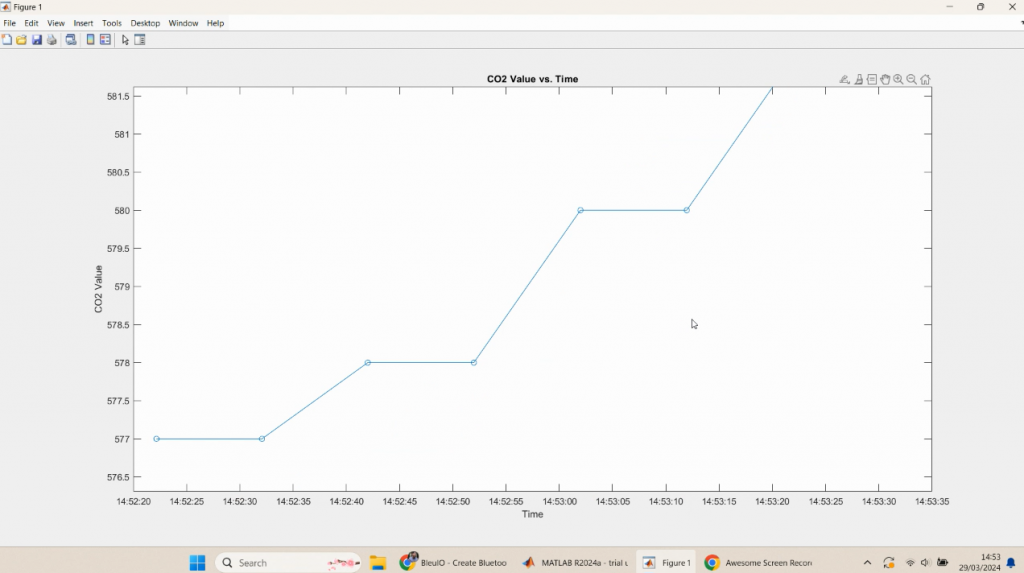
title('CO2 Value vs. Time');
% Store data in the figure's appdata
storedData.timeArray = [];
storedData.co2Array = [];
guidata(fig, storedData);
% Create a timer object to run scanAndDecode every 10 seconds
t = timer('ExecutionMode', 'fixedRate', 'Period', 10, ...
'TimerFcn', {@scanAndDecode, s, macaddress, plotHandle});
% Set the closerequestfcn callback to stop the timer and clear the serial port
set(fig, 'closerequestfcn', {@stopScript, t, s});
% Start the timer
start(t);
catch e
% Display any errors that occur
disp("An error occurred: " + e.message);
% Stop and delete the timer
if exist('t', 'var') && isvalid(t)
stop(t);
delete(t);
end
% Close the serial port
if exist('s', 'var') && isvalid(s)
clear s;
end
end
% Enable data cursors
dcm = datacursormode(gcf);
set(dcm, 'UpdateFcn', @customDataCursor);
% Custom data cursor function
function output_txt = customDataCursor(~, event_obj)
% Get the data cursor position
pos = get(event_obj, 'Position');
% Convert the x-coordinate (time) to a formatted string
timeString = datestr(pos(1), 'HH:MM:SS');
% Create the output text to display
output_txt = {['X: ', timeString], ['Y: ', num2str(pos(2))]}; % Customize as needed
end
function stopScript(~, ~, t, s)
% Stop and delete the timer
if exist('t', 'var') && isvalid(t)
stop(t);
delete(t);
end
% Close the serial port
if exist('s', 'var') && isvalid(s)
% Close the serial port
delete(s);
end
% Close the figure
delete(gcf);
end
Output
In this tutorial, we demonstrated how to read real-time air quality data from a BLE air quality monitoring device, such as HibouAir, using the BleuIO BLE USB dongle and MATLAB. By following the steps outlined in this tutorial, engineers, developers, and analysts can develop applications for monitoring air quality in various environments. This project has numerous potential applications, including indoor air quality monitoring in smart buildings, environmental monitoring in industrial settings, and health monitoring in healthcare facilities. By leveraging the power of BLE technology and MATLAB’s data analysis capabilities, users can gain valuable insights into air quality trends and make informed decisions to improve environmental conditions and human health.
In this tutorial, we’ll explore how to utilize BleuIO, a Bluetooth Low Energy (BLE) USB dongle, with Node.js for BLE application development. We’ll use the serialport library to communicate with BleuIO, enabling us to send AT commands and interact with BLE devices.
Node.js Backend (server.js): This file sets up an Express server to serve the HTML file and handles BLE interactions using BleuIO and serialport.
// server.js
const express = require('express');
const { SerialPort } = require('serialport');

const app = express();
const port = 3000;

// Serve the HTML file (optional)
app.get('/', (req, res) => {
  res.sendFile(__dirname + '/index.html');
});

// Endpoint to scan for BLE devices using BleuIO
app.get('/scanbledevice', (req, res) => {
  // Replace the following code with your BLE scanning logic
  const bleDevices = ['Device 1', 'Device 2', 'Device 3'];
  res.json(bleDevices);
});

// Start the server
app.listen(port, () => {
  console.log(`Server is running on http://localhost:${port}`);
});
BLE Scanning Logic: Implement BLE scanning logic using BleuIO and serialport in the server file (server.js). This module contains the function to scan for BLE devices using BleuIO.
// scanble.js
const { SerialPort } = require('serialport');

function scanBLE() {
  return new Promise((resolve, reject) => {
    // Use SerialPort to list available ports
    SerialPort.list()
      .then((ports) => {
        // Filter ports to find BleuIO device
        const blePorts = ports.filter((port) =>
          port.manufacturer.includes('Smart Sensor Devices')
        );

        if (blePorts.length === 0) {
          reject(new Error('BleuIO device not found'));
        }

        // Connect to the first found BleuIO device
        const blePort = new SerialPort({
          path: blePorts[0].path,
          baudRate: 115200
        });

        // Perform BLE scan
        blePort.write('AT+CENTRAL\r', (err) => {
          if (err) {
            reject(new Error('Error setting central role: ' + err.message));
          } else {
            blePort.write('AT+GAPSCAN=3\r', (err) => {
              if (err) {
                reject(new Error('Error initiating scan: ' + err.message));
              } else {
                setTimeout(() => {
                  // Read and parse scan results
                  const scanResults = blePort.read();
                  resolve(scanResults.split('\n'));
                }, 3500);
              }
            });
          }
        });
      })
      .catch((err) => {
        reject(new Error('Error listing serial ports: ' + err.message));
      });
  });
}

module.exports = { scanBLE };
HTML Frontend (index.html): This file provides a user interface (UI) to trigger BLE device scanning and display the results.
<!-- index.html -->
<!DOCTYPE html>
<html lang="en">
  <head>
    <!-- Include necessary meta tags and stylesheets -->
    <title>Scan BLE Device</title>
  </head>
  <body>
    <div class="container">
      <br />
      <br />
      <button class="btn btn-success" id="scanBtn">Scan for Devices</button>
      <div id="listScan"></div>
    </div>

    <!-- Include JavaScript for button click event -->
    <script>
      // JavaScript to handle button click event
    </script>
  </body>
</html>
Running the Application
Ensure your BleuIO dongle is connected to your computer.
Run the Node.js server
npm start
Open your web browser and navigate to http://localhost:3000.
Click the “Scan for Devices” button.
The list of nearby BLE devices will be displayed on the web page.
Output
In this tutorial, we’ve explored how to use BleuIO with Node.js via serial communication using the serialport library. You can extend this project by integrating more BLE functionalities and building a robust BLE application.
Feel free to customize and expand upon this project according to your requirements and explore the vast possibilities of BLE application development with Node.js and BleuIO!
In this project, we’ll create a system to monitor air quality in real-time using BleuIO (A Bluetooth Low Energy USB dongle). We’ll scan for an air quality monitoring device called HibouAir and decode the advertised data. The decoded air quality data will then be sent to the ThingsBoard cloud platform for visualization and monitoring.
Introduction to BleuIO
For this project, we’ll utilize a BLE USB dongle called BleuIO. BleuIO is a versatile Bluetooth low energy USB dongle that simplifies the development of BLE applications. It offers a range of AT commands, making it easy to interact with the dongle and create applications. BleuIO supports multiple platforms and programming languages. In our case, we’ll be using Python with the BleuIO Python library, available on PyPI.
About HibouAir
HibouAir is an advanced air quality monitoring device, HibouAir offers real-time data on various critical parameters including CO2 levels, particulate matter (PM 1.0, PM 2.5, PM 10), pressure, temperature, humidity, volatile organic compounds (VOCs), and noise levels. With its plug-and-play setup helps users to take immediate control of their indoor air quality.
About ThingsBoard
ThingsBoard is an open-source IoT platform that enables users to collect, store, visualize, and analyze data from connected devices in real-time. It provides a comprehensive set of features for building scalable and customizable IoT applications, including device management, data processing, rule engine, and customizable dashboards. With ThingsBoard, users can easily connect their devices, monitor their performance, and take actions based on real-time data insights. Its user-friendly interface and flexible architecture make it suitable for a wide range of IoT use cases, from industrial automation and smart cities to agriculture and healthcare. Additionally, ThingsBoard offers seamless integration with various third-party platforms and services, allowing users to leverage existing technologies and expand the capabilities of their IoT solutions.
Install the BleuIO Python library: First, we need to install the BleuIO Python library, which allows us to interact with the BleuIO USB dongle. You can install it using pip: pip install bleuio
Scan for nearby BLE devices: from bleuio_lib.bleuio_funcs import BleuIO import time my_dongle = BleuIO() my_dongle.at_central() my_dongle.at_findscandata('220069') # Replace '220069' with the device ID time.sleep(3) my_dongle.stop_scan()
Decode the advertised data last_element = my_dongle.scan_data[-1] data_part = json.loads(last_element[0])['data'] last_part = data_part.split(',')[-1].strip('"}') decoded_env_data = adv_data_decode(last_part)
Send data to ThingsBoard import requests api_endpoint = 'https://thingsboard.cloud/api/v1/YOUR_API_KEY/telemetry' response = requests.post(api_endpoint, json=decoded_env_data) if response.status_code == 200: print("Data sent successfully to ThingsBoard.") else: print("Failed to send data to ThingsBoard. Status code:", response.status_code)
Decoding Advertised Data
The advertised data contains encoded air quality data. We’ve implemented a function called adv_data_decode to decode this data based on the HibouAir datasheet. The decoded data includes parameters such as temperature, humidity, CO2 levels, etc.
Integration with ThingsBoard
We use the ThingsBoard cloud platform to visualize and monitor the air quality data. We send the decoded data to ThingsBoard via a POST request to the Telemetry API endpoint. If the request is successful, we receive a confirmation message.
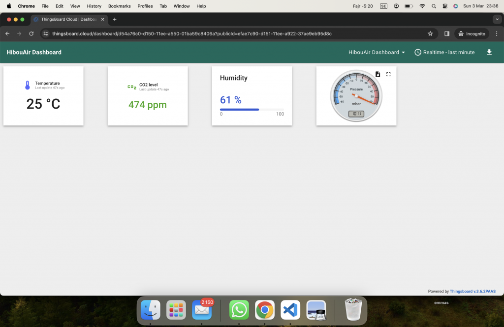
ThingsBoard setup
We have created a device called HibouAir and added pressure , temperature , co2, humidity widget attribute on my dashboard and this is how my dashboard looks. we can see latest data ( data updated 1 mins ago)
Code
Complete code is available on the following repository
With BleuIO and ThingsBoard integration, we’ve built a robust system for monitoring air quality in real-time. This project demonstrates the BleuIO can be used in ThingsBoard integrationto create IoT solutions for environmental monitoring.