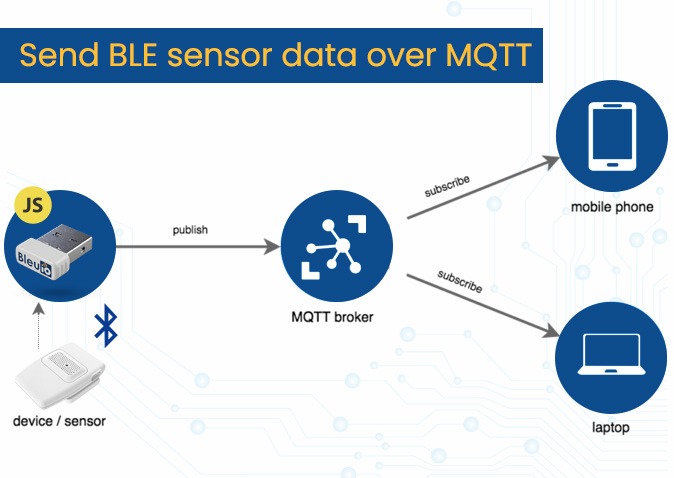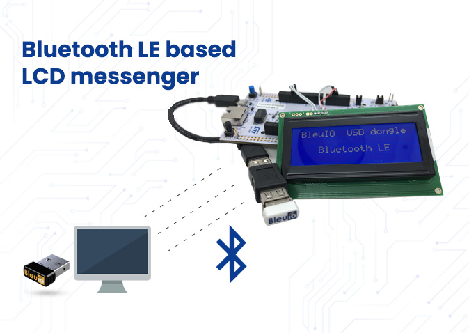
The aim of this project is to send message via Bluetooth using a web browser or smartphone to a LCD display which is connected to STM32 board.
1. Introduction
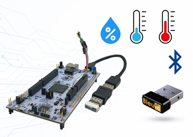
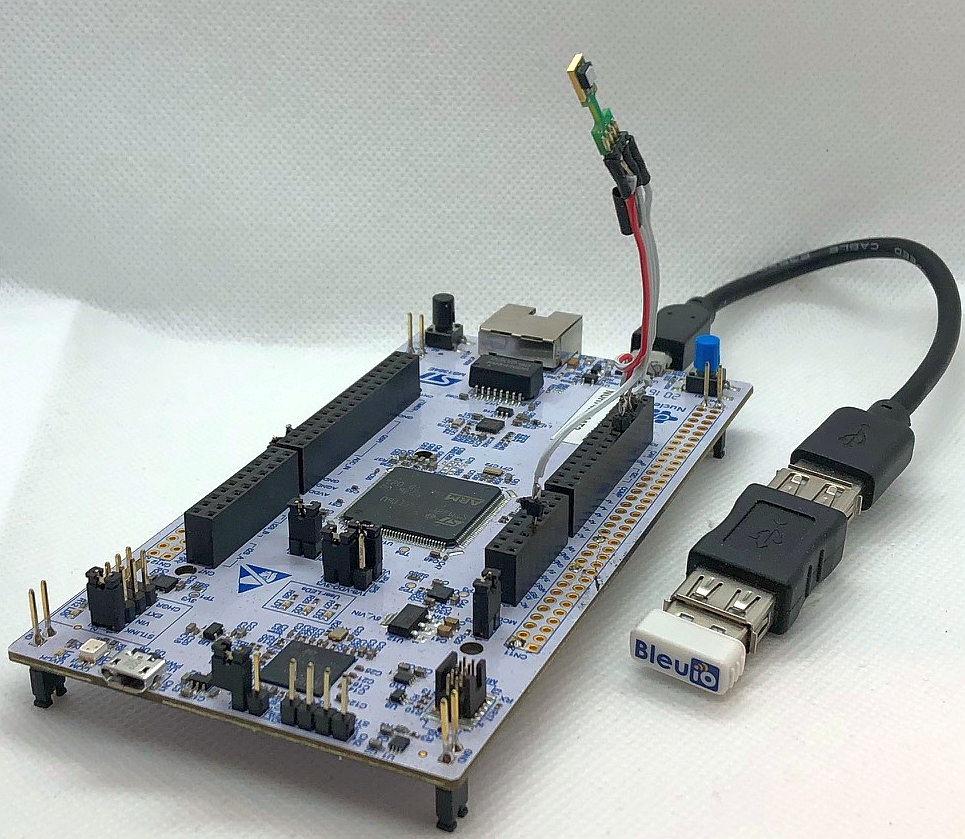
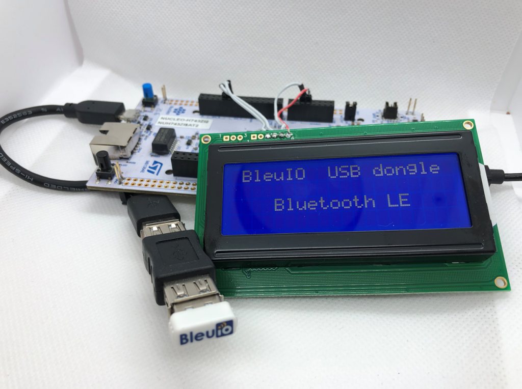
The project is based on STM32 Nucleo-144 which controls LCD display using BleuIO.
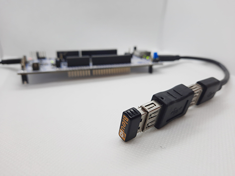
For this project, we will need two BleuIO USB dongles, one connected to the Nucleo board and the other to a computer, running the web script.
When the BleuIO Dongle is connected to the Nucleo boards USB port the STM32 will recognize it and directly start advertising. This allows the Dongle on the computer port connect with the web script.
With the web script on the computer, we can send message to LCD screen connected to STM32 using BleuIO.
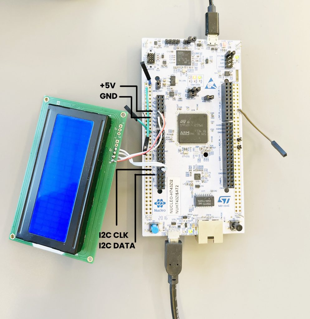
We have used a STM32 Nucleo-144 development board with STM32H743ZI MCU (STM32H743ZI micro mbed-Enabled Development Nucleo-144 series ARM® Cortex®-M7 MCU 32-Bit Embedded Evaluation Board) for this example. This development board has a USB host where we connect the BleuIO dongle.
If you want to use another setup you will have to make sure it support USB Host and beware that the GPIO setup might be different and may need to be reconfigured in the .ioc file.
About the Code
The project source code is available at Github.
https://github.com/smart-sensor-devices-ab/stm32_bleuio_lcd.git
Either clone the project, or download it as a zip file and unzip it, into your STM32CubeIDE workspace.
If you download the project as a zip file you will need to rename the project folder from ‘stm32_bleuio_lcd-master’ to ‘stm32_bleuio_lcd’
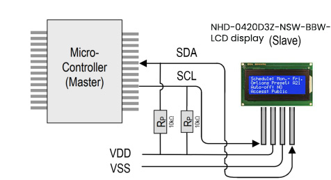
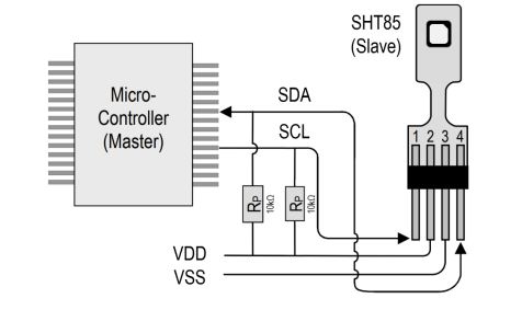
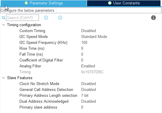
Connect the SDA to PF0 on the Nucleo board and SCL to PF1.
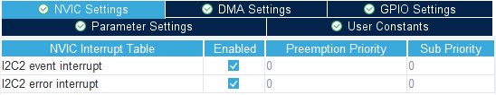
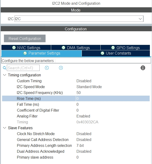
Then setup I2C2 in the STM32Cube ioc file as follows. (Make sure to change the I2C speed frequency to 50 KHz as per LCD display requirements.)


In the USBH_CDC_ReceiveCallback function in USB_HOST\usb_host.c we copy the CDC_RX_Buffer into a external variable called dongle_response that is accessable from the main.c file.
void USBH_CDC_ReceiveCallback(USBH_HandleTypeDef *phost)
{
  	if(phost == &hUsbHostFS)
  	{
  		// Handles the data recived from the USB CDC host, here just printing it out to UART
  		rx_size = USBH_CDC_GetLastReceivedDataSize(phost);
		HAL_UART_Transmit(&huart3, CDC_RX_Buffer, rx_size, HAL_MAX_DELAY);

		// Copy buffer to external dongle_response buffer
		strcpy((char *)dongle_response, (char *)CDC_RX_Buffer);

		// Reset buffer and restart the callback function to receive more data
		memset(CDC_RX_Buffer,0,RX_BUFF_SIZE);
		USBH_CDC_Receive(phost, CDC_RX_Buffer, RX_BUFF_SIZE);
  	}

  	return;
}
In main.c we create a simple intepreter so we can react to the data we are recieving from the dongle.
void dongle_interpreter(uint8_t * input)
{

	if(strlen((char *)input) != 0)
	{
		if(strstr((char *)input, "\r\nADVERTISING...") != NULL)
		{
			isAdvertising = true;
		}
		if(strstr((char *)input, "\r\nADVERTISING STOPPED") != NULL)
		{
			isAdvertising = false;
		}
		if(strstr((char *)input, "\r\nCONNECTED") != NULL)
		{
			isConnected = true;
			HAL_GPIO_WritePin(GPIOE, GPIO_PIN_1, GPIO_PIN_SET);
		}
		if(strstr((char *)input, "\r\nDISCONNECTED") != NULL)
		{
			isConnected = false;
			HAL_GPIO_WritePin(GPIOE, GPIO_PIN_1, GPIO_PIN_RESET);
		}


		if(strstr((char *)input, "L=0") != NULL)
		{

			isLightBulbOn = false;
			//HAL_GPIO_WritePin(Lightbulb_GPIO_Port, Lightbulb_Pin, GPIO_PIN_RESET);
			lcd_clear();

			writeToDongle((uint8_t*)DONGLE_SEND_LIGHT_OFF);

			uart_buf_len = sprintf(uart_tx_buf, "\r\nClear screen\r\n");
			HAL_UART_Transmit(&huart3, (uint8_t *)uart_tx_buf, uart_buf_len, HAL_MAX_DELAY);
		}

		if(strstr((char *)input, "L=1") != NULL)
		{
				isLightBulbOn = true;
				writeToDongle((uint8_t*)DONGLE_SEND_LIGHT_ON);


				lcd_clear();

				lcd_write(input);

		}

	}
	memset(&dongle_response, 0, RSP_SIZE);
}
We put the intepreter function inside the main loop.
/* Infinite loop */
  /* USER CODE BEGIN WHILE */
  while (1)
  {
    /* USER CODE END WHILE */
    MX_USB_HOST_Process();

    /* USER CODE BEGIN 3 */
    // Simple handler for uart input
    handleUartInput(uartStatus);

    // Inteprets the dongle data
    dongle_interpreter(dongle_response);

	// Starts advertising as soon as the Dongle is ready.
	if(!isAdvertising && !isConnected && isBleuIOReady)
	{
		HAL_Delay(200);
		writeToDongle((uint8_t*)DONGLE_CMD_AT_ADVSTART);
		isAdvertising = true;
	}
  }
  /* USER CODE END 3 */
Using the example project
What we will need
- Two BleuIO dongles (https://www.bleuio.com/)
- A board with a STM32 Microcontroller with a USB port. (A Nucleo-144 development board: NUCLEO-H743ZI2, was used developing this example. (https://www.st.com/en/evaluation-tools/nucleo-h743zi.html)
To connect the dongle to the Nucleo board a “USB A to Micro USB B”-cable with a USB A female-to-female adapter can be used.)
- STM32CubeIDE (https://www.st.com/en/development-tools/stm32cubeide.html)
- Liquid Crystal Display Module – NHD-0420D3Z-NSW-BBW-V3 (https://www.digikey.com/en/products/detail/newhaven-display-intl/NHD-0420D3Z-NSW-BBW-V3/2626390?s=N4IgTCBcDaIHIAkAiBaADAFjGpBmAWinAMoDqKAQheQGq4gC6AvkA)
Importing as an Existing Project
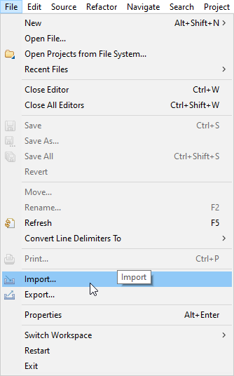
From STM32CubeIDE choose File>Import…

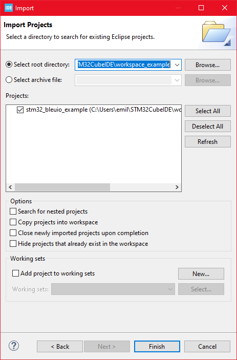
Then choose General>Existing Projects into Workspace then click ‘Next >’
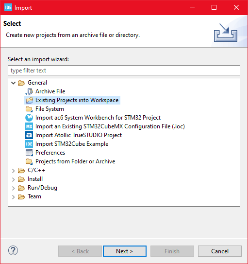
Make sure you’ve choosen your workspace in ‘Select root directory:’
You should see the project “stm32_bleuio_SHT85_example”, check it and click ‘Finish’.

Running the example
Upload the the code to STM32 and run the example. The USB dongle connect to STM32 will start advertising automatically.
Send Messages to LCD screen from a web browser
Connect the BleuIO dongle to the computer. Run the web script to connect to the other BleuIO dongle on the STM32. Now you can send messages to the LCD screen.
For this script to work, we need
- BleuIO USB dongle connected to the computer.
- BleuIO javascript library
- Chrome 78 or later, and you need to enable the #enable-experimental-web-platform-features flag in chrome://flags
- A web bundler – (parcel js)
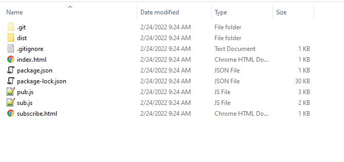
Create a simple Html file called index.html which will serve as the frontend of the script. This Html file contains some buttons that help connect and read advertised data from the remote dongle, which is connected to stm32.
<!DOCTYPE html>
<html lang="en">
  <head>
    <meta charset="UTF-8" />
    <meta http-equiv="X-UA-Compatible" content="IE=edge" />
    <meta name="viewport" content="width=device-width, initial-scale=1.0" />
    <link
      href="https://cdn.jsdelivr.net/npm/bootstrap@5.1.3/dist/css/bootstrap.min.css"
      rel="stylesheet"
      integrity="sha384-1BmE4kWBq78iYhFldvKuhfTAU6auU8tT94WrHftjDbrCEXSU1oBoqyl2QvZ6jIW3"
      crossorigin="anonymous"
    />
    <title>Send message to STM32 LCD display using Bluetooth LE</title>
  </head>
  <body class="mt-5">
    <div class="container mt-5">
      <h1 class="mb-5">Send message to STM32 LCD display using Bluetooth LE</h1>
      <button class="btn btn-success" id="connect">Connect</button>
      <div class="row">
        <div class="col-md-4">
          <form method="post" id="sendMsgForm" name="sendMsgForm">
            <div class="mb-3">
              <label for="msgToSend" class="form-label">Your Message</label>
              <input
                type="text"
                class="form-control"
                name="msgToSend"
                id="msgToSend"
                required
                maxlength="60"
              />
            </div>

            <button type="submit" class="btn btn-primary">Submit</button>
          </form>
        </div>
      </div>

      <br />
      <button class="btn btn-danger" id="clearScreen" disabled>
        Clear screen
      </button>
    </div>

    <script src="script.js"></script>
  </body>
</html>
Create a js file called script.js and include it at the bottom of the Html file. This js file uses the BleuIO js library to write AT commands and communicate with the other dongle.
import * as my_dongle from 'bleuio'
const dongleToConnect='[0]40:48:FD:E5:2F:17'
document.getElementById('connect').addEventListener('click', function(){
my_dongle.at_connect()
document.getElementById("clearScreen").disabled=false;
document.getElementById("connect").disabled=true;
document.getElementById("sendMsgForm").hidden=false;
})
document.getElementById("sendMsgForm").addEventListener("submit", function(event){
event.preventDefault()
console.log('here')
my_dongle.ati().then((data)=>{
//make central if not
if(JSON.stringify(data).includes("Peripheral")){
console.log('peripheral')
my_dongle.at_central().then((x)=>{
console.log('central now')
})
}
})
.then(()=>{
// connect to dongle
my_dongle.at_getconn().then((y)=>{
if(JSON.stringify(y).includes(dongleToConnect)){
console.log('already connected')
}else{
my_dongle.at_gapconnect(dongleToConnect).then(()=>{
console.log('connected successfully')
})
}
})
.then(()=>{
var theVal = "L=1 " + document.getElementById('msgToSend').value;
console.log('Message Send 1 '+theVal)
// send command to show data
my_dongle.at_spssend(theVal).then(()=>{
console.log('Message Send '+theVal)
})
})
})
});
document.getElementById('clearScreen').addEventListener('click', function(){
my_dongle.ati().then((data)=>{
//make central if not
if(JSON.stringify(data).includes("Peripheral")){
console.log('peripheral')
my_dongle.at_central().then((x)=>{
console.log('central now')
})
}
})
.then(()=>{
// connect to dongle
my_dongle.at_getconn().then((y)=>{
if(JSON.stringify(y).includes(dongleToConnect)){
console.log('already connected')
}else{
my_dongle.at_gapconnect(dongleToConnect).then(()=>{
console.log('connected successfully')
})
}
})
.then(()=>{
// send command to clear the screen
my_dongle.at_spssend('L=0').then(()=>{
console.log('Screen Cleared')
})
})
})
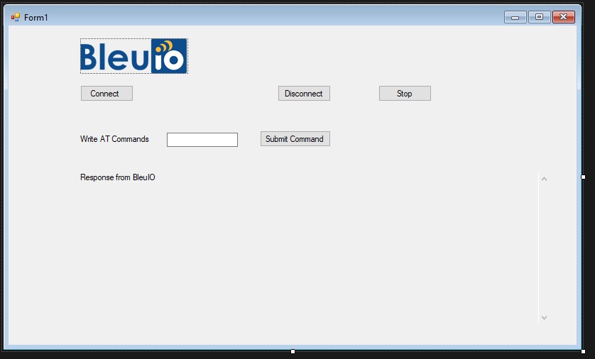
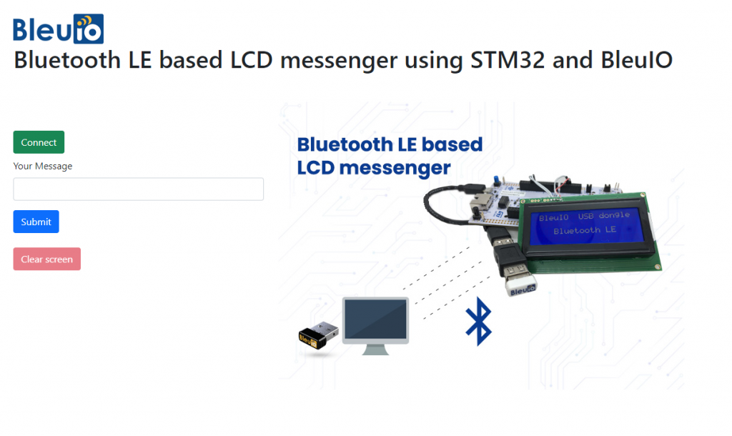
})The script has a button to connect to COM port on the computer. There is a text field where you can write your message. Your messages will be displayed on LCD screen connected to STM32 board.
To connect to the BleuIO dongle on the STM32, make sure the STM32 is powered up and a BleuIO dongle is connected to it.
Get the MAC address
Follow the steps to get the MAC address of the dongle that is connected to STM32
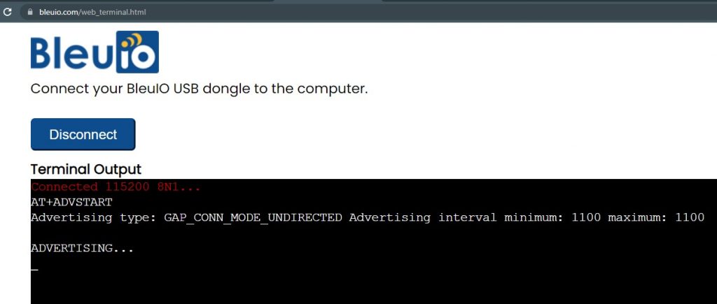
- Open this site https://bleuio.com/web_terminal.html and click connect to dongle.
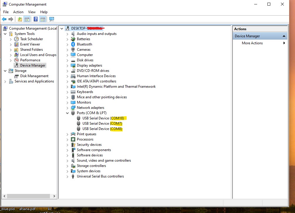
- Select the appropriate port to connect.
- Once it says connected, type ATI. This will show dongle information and current status.
- If the dongle is on peripheral role, set it to central by typing AT+CENTRAL
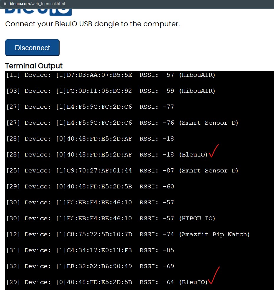
- Now do a gap scan by typing AT+GAPSCAN
- Once you see your dongle on the list ,stop the scan by pressing control+c
- Copy the ID and paste it into the script (script.js) line #2
Run the web script
You will need a web bundler. You can use parcel.js
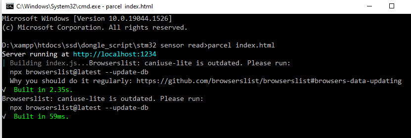
Once parcel js installed, go to the root directory of web script and type “parcel index.html”. This will start your development environment.
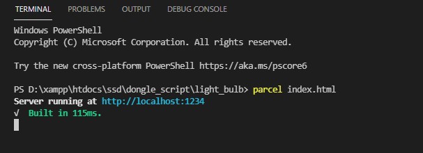
Open the script on a browser. For this example we opened http://localhost:1234
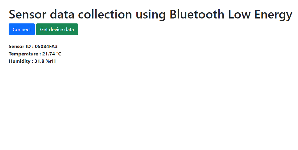
You can easily connect to the dongle and send your message to the LCD screen. The response will show on browser console screen.
The web script looks like this
Output
The message will show on the LCD screen.
Video of working project