BleuIO, a leading provider of Bluetooth Low Energy (BLE) solutions, has recently released an exciting new Python library update that supports its latest firmware version 2.3.0. This Python library is a powerful tool that allows developers to manage BLE custom services effortlessly. In this article, we will explore the key features of BleuIO’s Python library, its benefits, and how it simplifies the process of creating custom BLE services.
BleuIO’s Python Library Update
BleuIO’s Python library is a comprehensive set of tools and functions that interface with the BleuIO Bluetooth Low Energy USB dongle. The latest update, which supports firmware version 2.3.0, introduces enhanced capabilities for managing custom BLE services, making it easier for developers to create and deploy custom services for their applications.
The Python library comes with a range of convenient AT commands that can be used to control various aspects of the BleuIO dongle, including scanning, advertising, connecting, and, most importantly, setting up custom services. With just a few lines of Python code, developers can now configure their own custom BLE services, tailoring them to meet the specific requirements of their projects.
Benefits of the Python Library for Custom Services
The new Python library from BleuIO offers several benefits that simplify the process of working with custom BLE services:
- Ease of Use: The library abstracts the complexities of interacting with the BLE dongle through simple and easy-to-understand Python functions. This allows even those new to BLE development to get started quickly.
- Time Efficiency: By providing high-level functions for custom service setup, the library saves developers valuable time. No need to write low-level code for every aspect of the BLE service creation; instead, developers can focus on implementing the unique features of their applications.
- Flexible Customization: With the library, developers have complete control over the configuration of custom services. They can define custom UUIDs, set permissions, properties, and values for each characteristic, tailoring the service to their specific use case.
- Real-time Updates: The example script demonstrates how to continuously update the values of characteristics and notify/indicate subscribers. This feature is invaluable for applications that require real-time data exchange.
Creating a Custom Service with BleuIO’s Python Library
Let’s take a look at a sample Python script that showcases how to create a custom BLE service using BleuIO’s Python library:
# (C) 2023 Smart Sensor Devices AB

import time
from datetime import datetime

from bleuio_lib.bleuio_funcs import BleuIO

# This example will show how to setup your own service
# Press Ctrl-C to exit the script.


# Scan result Callback function
def my_scan_callback(scan_input):
    print("\n\nmy_scan_callback: " + str(scan_input))


# Event Callback function
def my_evt_callback(scan_input):
    print("\n\nmy_evt_callback: " + str(scan_input))


# Start BleuIO
my_dongle = BleuIO()
# Register callback functions for scan results and events
my_dongle.register_evt_cb(my_evt_callback)
my_dongle.register_scan_cb(my_scan_callback)

# Run ATI Command
resp = my_dongle.ati()
print(resp.Cmd)
print(resp.Ack["errMsg"])
print(resp.Rsp)

print("My Role: " + my_dongle.status.role)
print("Is Adv: " + str(my_dongle.status.isAdvertising))
print("Is Connected: " + str(my_dongle.status.isConnected))

# Set role to dual if it isn't set already
if not my_dongle.status.role == my_dongle.gaproles.DUAL:
    resp = my_dongle.at_dual()
    print(resp.Cmd)
    print(resp.Ack)

# Disconnect if we're connected
if my_dongle.status.isConnected:
    resp = my_dongle.at_gapdisconnectall()
    print(resp.Cmd)
    print(resp.Ack)

# Stop Advertising if we're advertising
if my_dongle.status.isAdvertising:
    resp = my_dongle.at_advstop()
    print(resp.Cmd)
    print(resp.Ack)

# Stop custom service just in case it had been started previously
resp = my_dongle.at_customservice_stop()
print(resp.Cmd)
print(resp.Ack)

# Service

# Set service UUID
resp = my_dongle.at_customservice(
    0, my_dongle.UUID, "ee6ec068-7447-4045-9fd0-593f3ba3c2ee"
)
print(resp.Cmd)
print(resp.Ack)

# Characteristic 1

# Set characteristic 1 UUID
resp = my_dongle.at_customservice(
    2, my_dongle.UUID, "018f55d9-d747-4c4e-a87b-e9b074ffd2b6"
)
print(resp.Cmd)
print(resp.Ack)

# Set characteristic 1 value length
resp = my_dongle.at_customservice(1, my_dongle.CHAR_LENGTH, "100")
print(resp.Cmd)
print(resp.Ack)

# Set characteristic 1 value
# Here we set it to the current time in hours, minutes and seconds format.
cbTime = datetime.now()
char1_data = cbTime.strftime("%H:%M:%S")
resp = my_dongle.at_customservice(1, my_dongle.CHAR_VALUE, char1_data)
print(resp.Cmd)
print(resp.Ack)

# Set characteristic 1 permissions
resp = my_dongle.at_customservice(1, my_dongle.CHAR_PERMISSION, "R")
print(resp.Cmd)
print(resp.Ack)

# Set characteristic 1 properties
# We set it to Read and Notify
resp = my_dongle.at_customservice(1, my_dongle.CHAR_PROPERTY, "NR")
print(resp.Cmd)
print(resp.Ack)

# Characteristic 2

# Set characteristic 2 UUID
resp = my_dongle.at_customservice(
    2, my_dongle.UUID, "a693ba2c-f0df-40cb-aea7-8ae47281d997"
)
print(resp.Cmd)
print(resp.Ack)

# Set characteristic 2 value length
resp = my_dongle.at_customservice(2, my_dongle.CHAR_LENGTH, "100")
print(resp.Cmd)
print(resp.Ack)

# Set characteristic 2 value
# Here we set it to the current time in month, days and years format.
cbTime = datetime.now()
char2_data = cbTime.strftime("%m/%d/%Y")
resp = my_dongle.at_customservice(2, my_dongle.CHAR_VALUE, char2_data)
print(resp.Cmd)
print(resp.Ack)

# Set characteristic 2 permissions
resp = my_dongle.at_customservice(2, my_dongle.CHAR_PERMISSION, "R")
print(resp.Cmd)
print(resp.Ack)

# Set characteristic 2 properties
# We set it to Read and Indicate
resp = my_dongle.at_customservice(2, my_dongle.CHAR_PROPERTY, "IR")
print(resp.Cmd)
print(resp.Ack)

# Here we check that the service data we set has gone in
resp = my_dongle.at_customservice()
print(resp.Cmd)
print(resp.Ack)
print(resp.Rsp)
print(resp.End)

# Here we start the custom service so next time we advertise and someone connects they will see the new service
resp = my_dongle.at_customservice_start()
print(resp.Ack)

# Here we start advertising so other devices can detect us and connect
resp = my_dongle.at_advstart()
print(resp.Ack)

# Going in a never ending loop that will just update the values of Characteristic 1 and 2 every second.
# If anyone is subscribed we will notify/indicate them.
while True:
    cbTime = datetime.now()
    notiCharTime = cbTime.strftime("%H:%M:%S")
    resp = my_dongle.at_customservice(1, my_dongle.CHAR_VALUE, notiCharTime)
    print(resp.Cmd)
    print(resp.Ack)

    indiCharTime = cbTime.strftime("%m/%d/%Y")
    resp = my_dongle.at_customservice(2, my_dongle.CHAR_VALUE, indiCharTime)
    print(resp.Cmd)
    print(resp.Ack)
    time.sleep(1)
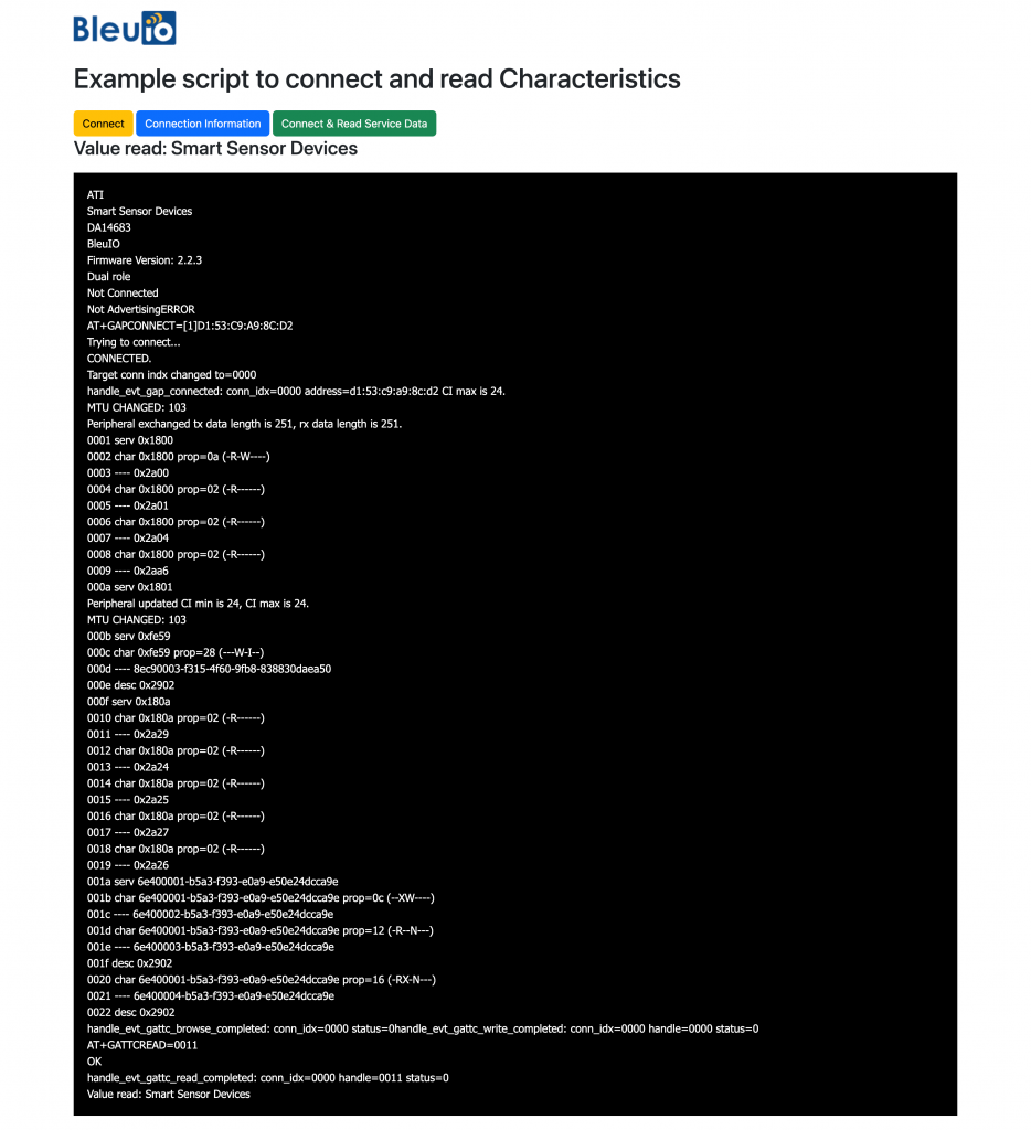
The example script demonstrates the process of setting up a custom service with two characteristics. Characteristic 1 holds the current time in hours, minutes, and seconds format, while Characteristic 2 contains the date in month, day, and year format. The script registers callbacks for scan results and events, sets up the service UUID, characteristic UUIDs, permissions, properties, and starts advertising the custom service.
With BleuIO’s Python library and the user-friendly AT commands, BLE application development becomes accessible to a wider audience, fostering a new era of creative and groundbreaking IoT solutions. Developers can explore the BleuIO Python library further by visiting the official PyPI page (https://pypi.org/project/bleuio/) and start harnessing the power of BLE for their projects.