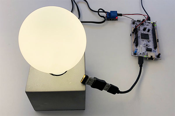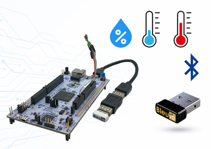
The project is showcasing a simple way of using the the BleuIO Dongle to advertise data that the STM32 reads from a sensor which is connected to the STM32 Nucleo-144.
Requirments :
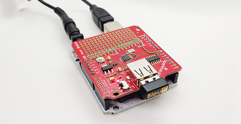
- A BleuIO dongle (https://www.bleuio.com/)
- A SHT85 sensor (https://sensirion.com/products/catalog/SHT85/)
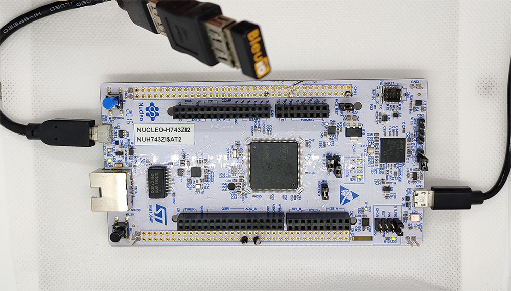
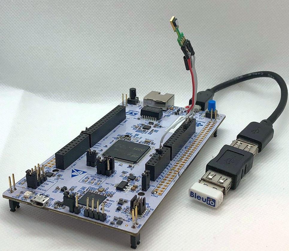
- A board with a STM32 Microcontroller with a USB port. (A Nucleo-144 development board: NUCLEO-H743ZI2, was used developing this example. (https://www.st.com/en/evaluation-tools/nucleo-h743zi.html)
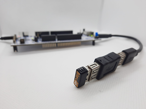
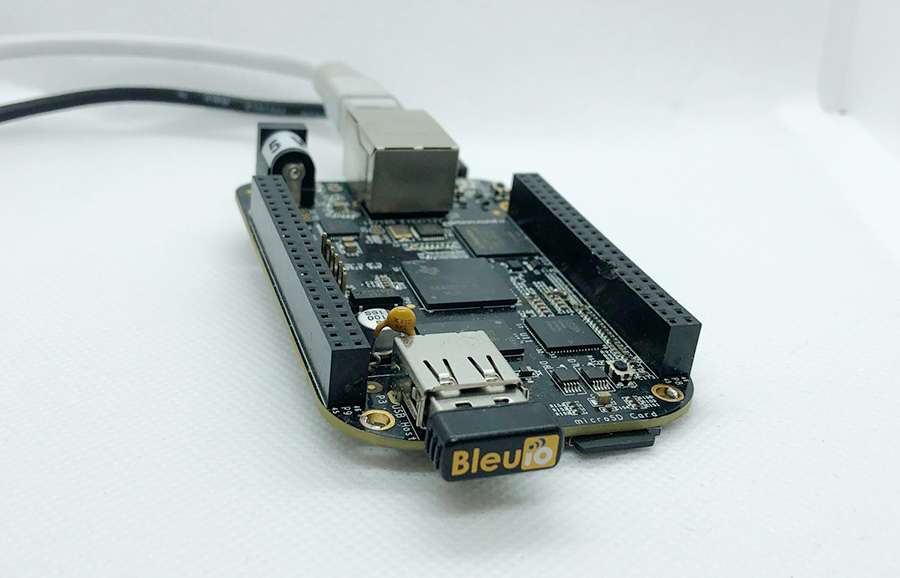
- To connect the dongle to the Nucleo board we used a “USB A to Micro USB B”-cable with a USB A female-to-female adapter.)
- STM32CubeIDE (https://www.st.com/en/development-tools/stm32cubeide.html)
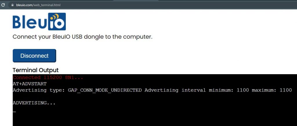
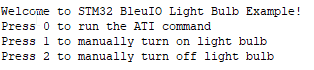
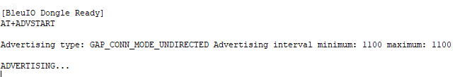
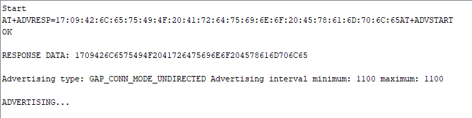
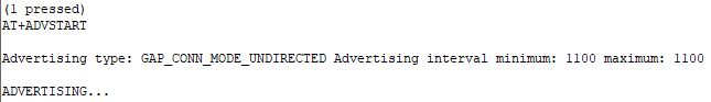
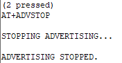
When the BleuIO Dongle is connected to the Nucleo boards USB port, the STM32 will recognize it and start advertising the sensor values that it reads from the SHT85 along with the sensor serial number. It will update these values every 10 seconds.
Setup the project
Part 1 : Download the project
Get project HERE
https://github.com/smart-sensor-devices-ab/stm32_bleuio_SHT85_example
Either clone the project, or download it as a zip file and unzip it, into your STM32CubeIDE workspace.
Part 2 : Importing as an Existing Project
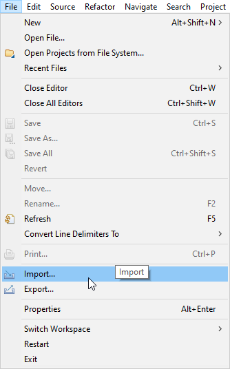
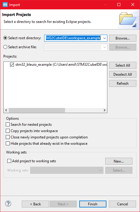
From STM32CubeIDE choose File>Import…

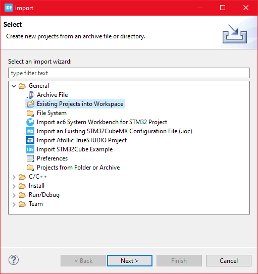
Then choose General>Existing Projects into Workspace then click ‘Next >’

Make sure you’ve choosen your workspace in ‘Select root directory:’
You should see the project “stm32_bleuio_SHT85_example”, check it and click ‘Finish’.
If you download the project as a zip file you will need to rename the project folder from ‘stm32_bleuio_SHT85_example-master’ to ‘stm32_bleuio_SHT85_example’
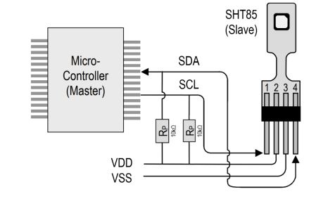
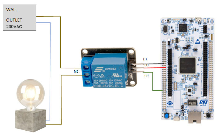
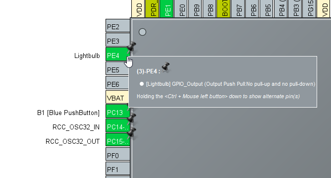
Connect the SDA to PF0 on the Nucleo board and SCL to PF1.
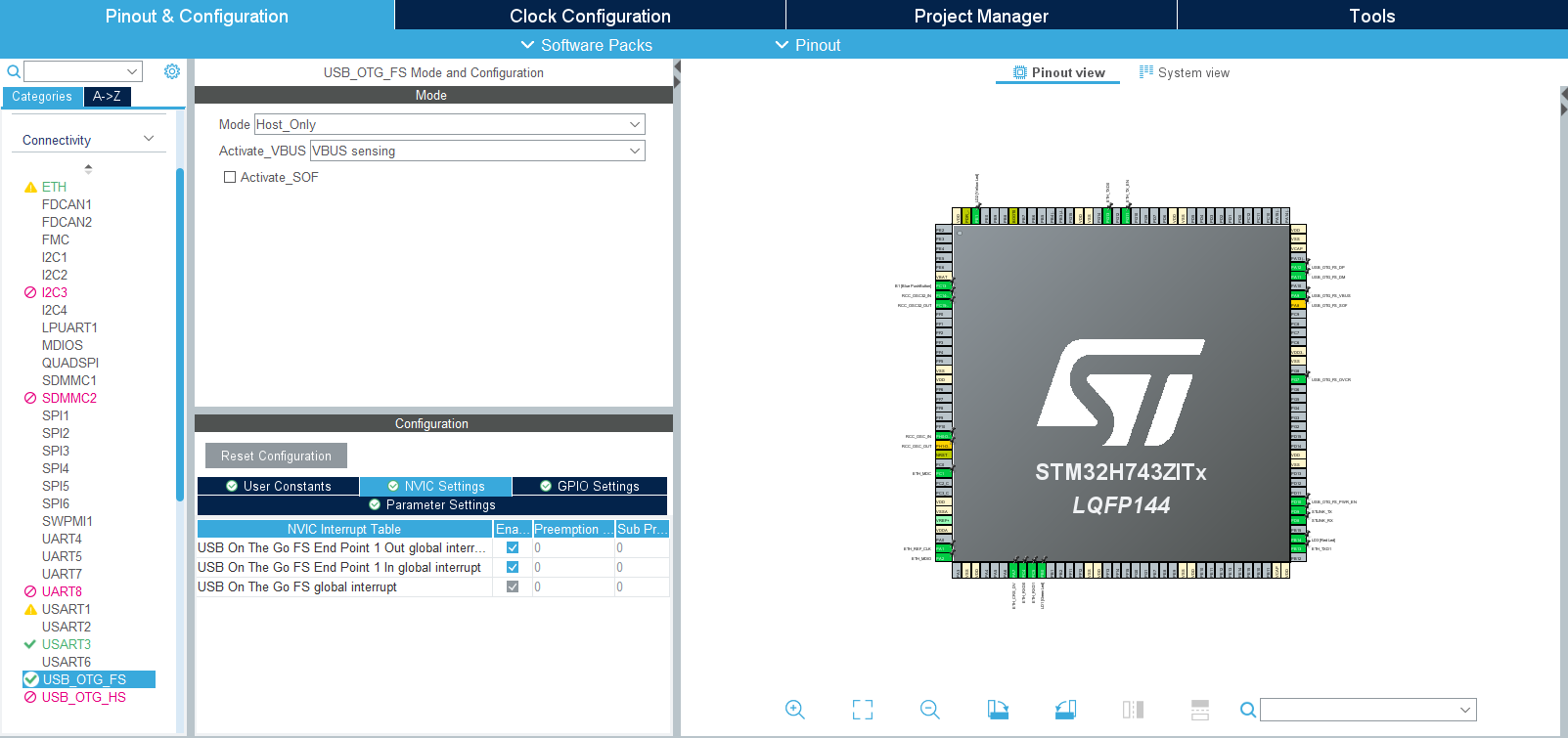
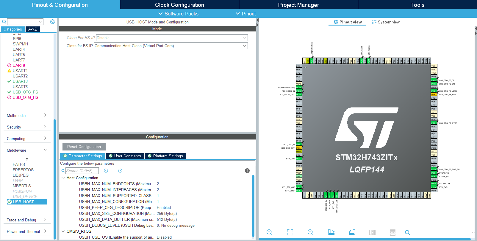
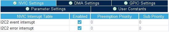
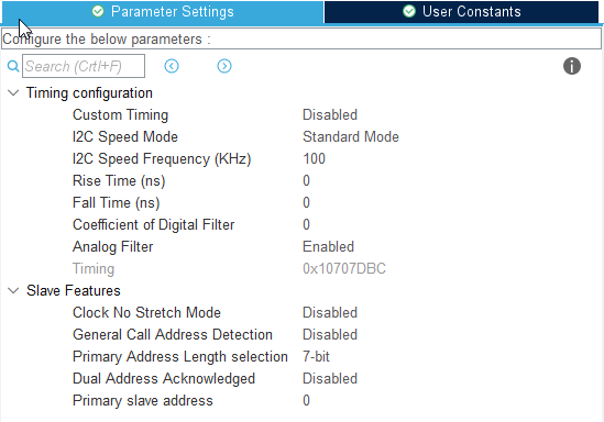
Then setup I2C2 in the STM32Cube ioc file like this:

Running the example
In STMCubeIDE click the hammer icon to build the project.
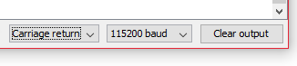
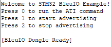
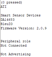
- Open up the ‘STMicroelectronics STLink Viritual COM Port’ with a serial terminal emulation program like TeraTerm, Putty or CoolTerm.
Baudrate: 115200
Data Bits: 8
Parity: None
Stop Bits: 1
Flow Control: None
- In STMCubeIDE click the green play button to flash and run it on your board. The first time you click it the ‘Run Configuration’ window will appear. You can just leave it as is and click run.
- Connect the BleuIO Dongle.
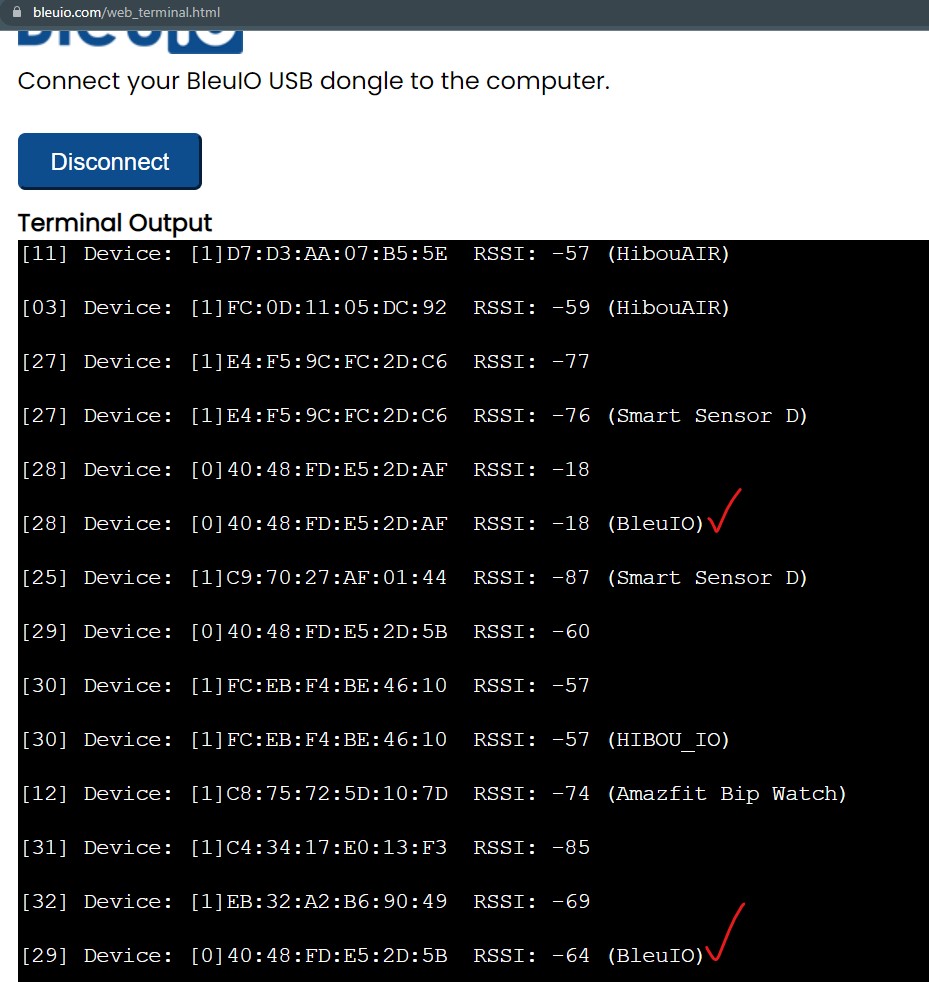
Access sensor data from a web browser
We wrote a simple script that connects to the BleuIO dongle and reads advertised data from STM32.
For this script to work, we need
- BleuIO USB dongle connected to the computer.
- BleuIO javascript library
- Chrome 78 or later, and you need to enable the #enable-experimental-web-platform-features flag in chrome://flags
- A web bundler – (parcel js)
Steps
Create a simple Html file called index.html which will serve as the frontend of the script. This Html file contains some buttons that help connect and read advertised data from the remote dongle, which is connected to stm32.
<!DOCTYPE html>
<html lang="en">
  <head>
    <!-- Required meta tags -->
    <meta charset="utf-8" />
    <meta name="viewport" content="width=device-width, initial-scale=1" />

    <!-- Bootstrap CSS -->
    <link
      href="https://cdn.jsdelivr.net/npm/bootstrap@5.1.3/dist/css/bootstrap.min.css"
      rel="stylesheet"
      integrity="sha384-1BmE4kWBq78iYhFldvKuhfTAU6auU8tT94WrHftjDbrCEXSU1oBoqyl2QvZ6jIW3"
      crossorigin="anonymous"
    />

    <title>STM32 Read sensor value</title>
  </head>
  <body>
    <div class="container mt-5">
      <h1>Sensor data collection from stm32 using Bluetooth Low Energy</h1>
      <button id="connect" class="btn btn-primary">Connect</button>
      <button id="getdata" class="btn btn-success">Get device data</button>
      <div id="loader"></div>
      <br />
      <div id="response" class="fw-bold"></div>

      <script src="./index.js"></script>
    </div>
  </body>
</html>
Create a js file called script.js and include it at the bottom of the Html file. This js file uses the BleuIO js library to write AT commands and communicate with the other dongle.
import * as my_dongle from 'bleuio'

//connect to BleuIO
document.getElementById('connect').addEventListener('click', function(){
  my_dongle.at_connect()
})
//get sensor data
document.getElementById('getdata').addEventListener('click', function(){
  document.getElementById('loader').innerHTML = 'Loading'
  //set the BleuIO dongle into dual role
    my_dongle.at_dual().then(()=>{
      // sensor id of the device that we are trying to get data from
      let sensorID='05084FA3'

      //look for advertised data of with the sensor id
        my_dongle.at_findscandata(sensorID,4).then(x=>{

          //split the advertised data from the respnse
          let advdata= x[x.length-1].split(" ").pop()

          //trim the advertised string to only get sensor response
          const result = advdata.split(sensorID).slice(1).join(sensorID)

          //get temperature and humidity value
          let temp = result.substring(0, 4);
          let hum = result.substring(4, 8);

          //convert from hex to decimal and device by 100
          temp = parseInt(temp, 16)/100
          hum = (parseInt(hum, 16)/100).toFixed(1)

          document.getElementById('loader').innerHTML = ''
          document.getElementById('response').innerHTML = `Sensor ID : 05084FA3 <br/>
          Temperature : ${temp} °C<br/>
          Humidity : ${hum} %rH<br/>`
        })
    })

  })
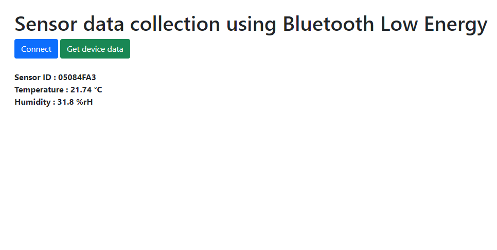
The script js file has two button actions; connect and read advertised data.
We also need to update the Sensor ID on line 13 of script js. The Sensor ID of this example project is 05084FA3, which we got from SHT85.
Therefore this script looks for advertised data that contains sensor ID 05084FA3. After getting advertised data , we split the temperature and humidity information and show it on our index.html page.
Now we need a web bundler. We can use parcel.js
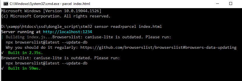
Once parcel js installed, lets go to the root directory and type “parcel index.html”. This will start our development environment.
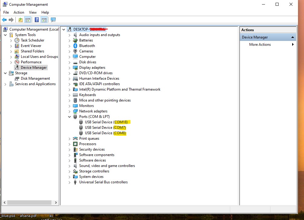
Lets open the script on a browser and select the right port where the dongle is connected.
The web script is available on web script folder of the GitHub repository.