Bluetooth Low Energy (BLE) technology has become increasingly popular for creating wireless applications with low power consumption. In this tutorial, we’ll explore the process of scanning for nearby BLE devices, connecting to a specific device, and reading characteristics using the BleuIO BLE USB dongle. The tutorial is designed for Linux/MacOS environments.
Introduction to BleuIO
BleuIO is a versatile Bluetooth Low Energy USB dongle that simplifies BLE application development. It supports the AT command set, allowing developers to interact with the dongle using familiar commands. Whether you’re a seasoned BLE developer or just getting started, BleuIO offers a convenient and efficient way to work with BLE applications.
Forget complex libraries and complicated programming. Develop BLE applications effortlessly through simple AT commands.
Setting Up the Development Environment
Before diving into the tutorial, ensure you have the following prerequisites:
Python: Ensure that Python is installed on your system.
Writing the BLE Application Script
The provided Python script demonstrates the process of connecting to the BleuIO dongle, scanning for nearby BLE devices, and reading characteristics. Let’s break down the key components of the script:
# Importing necessary modules
import serial
import time

# Establishing connection to the BleuIO dongle
connecting_to_dongle = 0
print("Connecting to dongle...")

while connecting_to_dongle == 0:
    try:
        # Configuring the serial connection
        console = serial.Serial(
            port='/dev/cu.usbmodem4048FDE52CF21',
            baudrate=57600,
            parity="N",
            stopbits=1,
            bytesize=8,
            timeout=0
        )
        if console.is_open.__bool__():
            connecting_to_dongle = 1
    except:
        print("Dongle not connected. Please reconnect Dongle.")
        time.sleep(5)

# Sending commands to the BleuIO dongle
console.write(str.encode("AT+CENTRAL"))
console.write('\r'.encode())
time.sleep(0.1)
console.write(str.encode("AT+GAPSCAN=3"))
console.write('\r'.encode())
time.sleep(3.5)
console.write(str.encode("AT+GAPCONNECT=[1]D1:79:29:DB:CB:CC"))
console.write('\r'.encode())
console.write(str.encode("AT+GATTCREAD=0013"))
console.write('\r'.encode())

# Waiting for the dongle to respond
time.sleep(1)
out = ""
while console.inWaiting() > 0:
    out += console.read(console.inWaiting()).decode()
else:
    if not out.isspace():
        print(out + " ")
        out = " "
Explanation:
1. Connecting to BleuIO:
Download and install a serial terminal emulator like screen or minicom.
Ensure your dongle is connected and note its port (e.g., /dev/cu.usbmodem4048FDE52CF21).
Run the script with the correct port and baudrate (57600) in your terminal.
The script attempts connection until successful, then sends essential AT commands:
AT+CENTRAL: Configures BleuIO as a central device (scanning/connecting).
AT+GAPSCAN=3: Starts scanning for BLE devices for 3 seconds.
2. Selecting and Connecting:
The scan results will appear in your terminal.
Identify the desired device, usually by name or MAC address.
Replace D1:79:29:DB:CB:CC in the script with your device’s MAC address.
Send AT+GAPCONNECT=[1]D1:79:29:DB:CB:CC to connect to the device (replace the mac address with your desired device if needed).
3. Reading a Characteristic:
Every BLE device exposes characteristics containing specific data.
Replace 0013 in AT+GATTCREAD with the characteristic’s UUID to read its value.
This script reads the characteristic with UUID 0013 and prints its value. Currently its showing the device type.
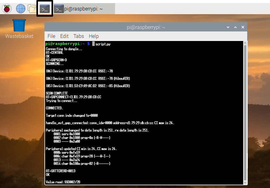
The outout
The output will be shown on the screen as
Value read: SSD002/2B
Hex: 0x5353443030322F3242
Size: 9
Understanding the Code:
The script uses serial library to communicate with BleuIO via AT commands.
While loops ensure connection success and read all available data.
The script parses output and filters empty space to avoid repetitive printing.
In this tutorial, we’ve covered the basics of working with the BleuIO BLE USB dongle on Linux/MacOS systems. The simplicity of the AT command interface and cross-platform compatibility make BleuIO an excellent choice for BLE application development. Experiment with the provided script, explore additional AT commands from BleuIO, and unlock the full potential of BLE applications with BleuIO. Happy coding!
In this tutorial, we will walk you through the process of creating a Home Assistant integration to read air quality data from a BLE air quality monitor called HibouAir. To accomplish this, we’ll be using BleuIO, a BLE USB dongle, to read data via the serial port. BleuIO comes equipped with a Python library that simplifies the project significantly. This integration provides real-time updates of various air quality parameters, such as pressure, temperature, humidity, VOC, CO2 and Particle Matters.
Prerequisites
Before we dive into the implementation, make sure you have the following prerequisites in place:
HibouAir Air Quality Monitor: Ensure you have a HibouAir air quality monitor. You can obtain it from the official source.
BleuIO BLE USB Dongle: Acquire a BleuIO BLE USB dongle to facilitate communication with the HibouAir monitor.
Host Computer: We’ll use a Windows-based host computer in this example.
Home Assistant: Install Home Assistant and have it up and running. You can run Home Assistant within a virtual machine using VirtualBox, as demonstrated in this tutorial.
Implementation
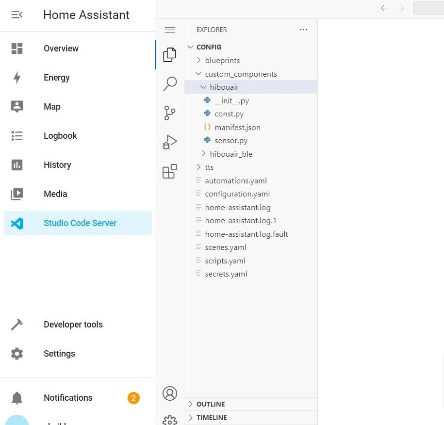
Let’s start by setting up the Home Assistant integration for HibouAir and BleuIO. You can find the complete code for this project on the following GitHub repository:
platform: Specifies the integration to use, which is hibouair_ble in this case.
scan_interval: Sets the interval for scanning and updating data. The example uses 120 seconds (2 minutes) for real-time data updates. Adjust this value according to your preference.
3. Restart Home Assistant
After updating the configuration, save the file and restart your Home Assistant instance. This will enable the integration.
4. Monitor Air Quality Data
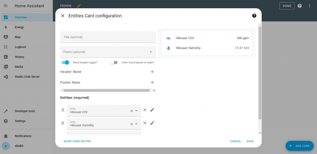
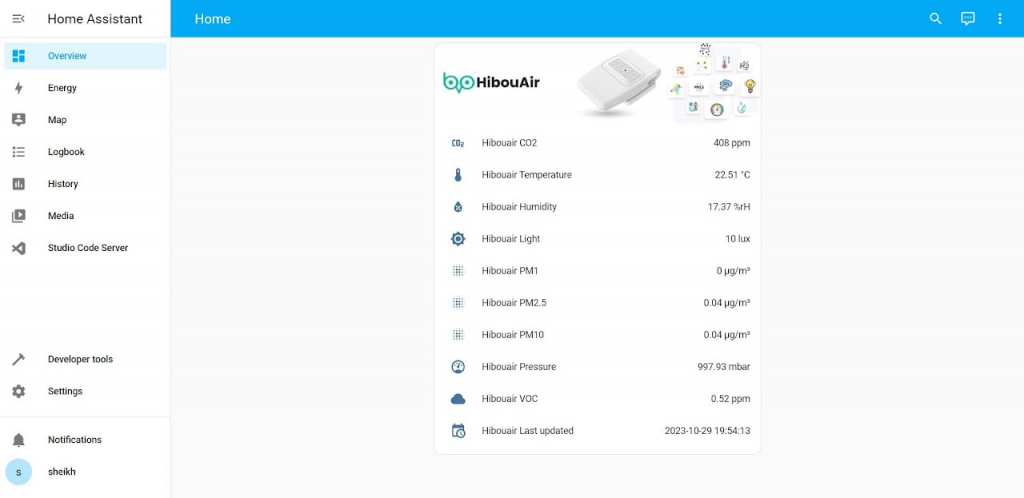
Once Home Assistant is restarted, you should be able to see entities representing various air quality parameters with the hibouair_ble prefix. These parameters may include pressure, temperature, humidity, VOC, CO2, and more. The air quality data will update every 2 minutes, providing real-time information about your environment.
After setting up the dashboard with the Hibouair_ble entities , the dashboard looks like this
This integration is a simple example, and you can further customize and automate your smart home based on the data collected from the HibouAir monitor. Feel free to adapt the code to your specific requirements and enhance the capabilities of your Home Assistant setup.
With the combination of HibouAir and BleuIO, you can effortlessly create a home automation system that ensures your environment remains healthy and comfortable.
Bluetooth Low Energy (BLE) is a wireless communication technology commonly used in various IoT and wearable devices. With the right tools and libraries, working with BLE devices on Linux becomes easy and efficient. In this tutorial, we’ll explore how to use the BleuIO dongle and the associated Python library to scan for nearby BLE devices, connect to a device, and read its characteristics, specifically the device name.
Prerequisites
Before we begin, ensure you have the following:
BleuIO Dongle: You’ll need a BleuIO dongle, a versatile BLE device capable of working on any platform.
BleuIO Python Library: Install the BleuIO Python library, which provides the necessary tools for interacting with the BleuIO dongle. You can install it using pip:
pip install bleuio
Now that you have the prerequisites in place, let’s dive into the process.
Step 1: Setting up the Python Script
First, let’s set up a Python script to work with the BleuIO dongle. Here’s a script that demonstrates how to scan for nearby BLE devices, connect to one of them, and read characteristics.
import time
from datetime import datetime
from bleuio_lib.bleuio_funcs import BleuIO

# Creating a callback function for scan results
def my_scan_callback(scan_input):
    print("\n\nmy_scan_callback: " + str(scan_input))

# Creating a callback function for events
def my_evt_callback(evt_input):
    cbTime = datetime.now()
    currentTime = cbTime.strftime("%H:%M:%S")
    print("\n\n[" + str(currentTime) + "] my_evt_callback: " + str(evt_input))

# Initiating the BleuIO dongle
my_dongle = BleuIO()

# Registering the callback functions
my_dongle.register_evt_cb(my_evt_callback)
my_dongle.register_scan_cb(my_scan_callback)

# Switch to Central or Dual Gap Role
my_dongle.at_dual()

# Start scanning for devices
my_dongle.at_gapscan(3)

# Wait for a few seconds to allow devices to be discovered
time.sleep(4)

# Connect to a device using its MAC address
my_dongle.at_gapconnect('[1]D1:79:29:DB:CB:CC')

# Wait for the connection to establish
time.sleep(4)

# Read characteristics with handle '0003', which contains the device name
my_dongle.at_gattcread('0003')

# Wait briefly
time.sleep(1)
Step 2: Running the Script
Save the script to a Python file, for example, bleuio_ble_tutorial.py. Then, run the script using your Python interpreter.
The script performs the following actions:
Initiates the BleuIO dongle and sets up callback functions for scan results and events.
Switches to Central or Dual Gap Role.
Scans for nearby BLE devices for a specified duration (3 seconds in this example).
Connects to a specific device using its MAC address.
Waits for the connection to establish.
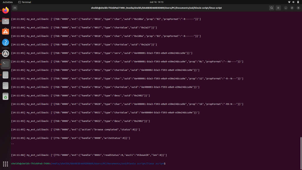
Reads the characteristics with handle ‘0003’, which typically contains the device name.
Waits briefly before exiting.
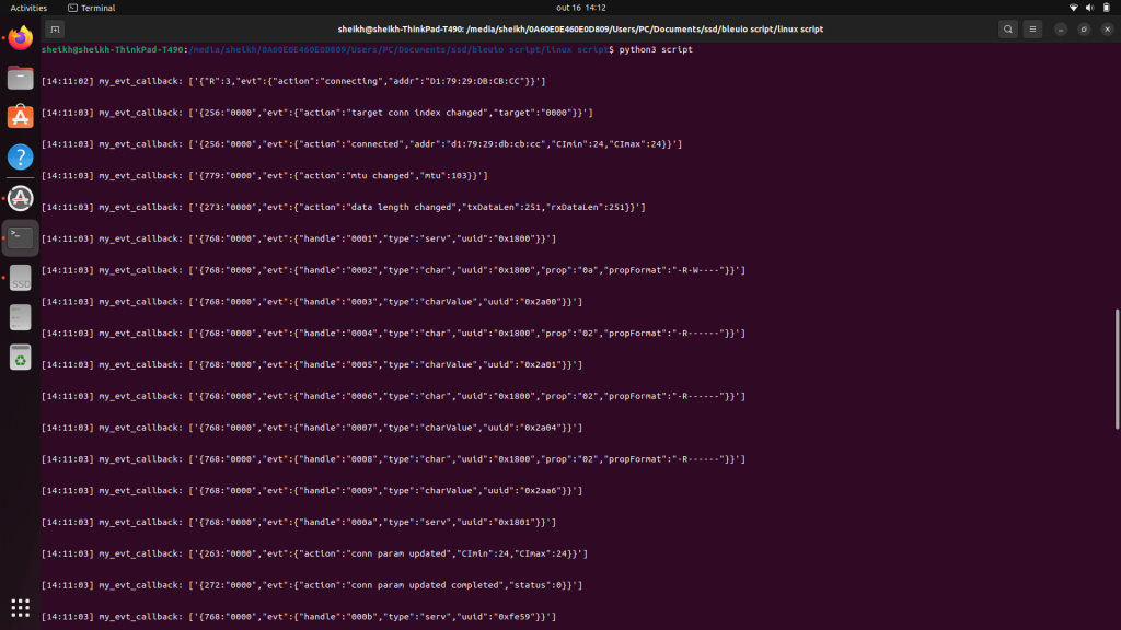
The scan results and characteristic data will be displayed on the terminal.
Output :
Working with BLE devices on Linux using the BleuIO dongle and Python library is a straightforward process. You can use this script as a starting point to interact with BLE devices and further develop your BLE applications. Remember to customize the script to suit your specific needs, and explore the wealth of possibilities that BLE technology offers in the world of IoT and wireless communication.
Bluetooth Low Energy (BLE) technology has revolutionized the way we interact with devices wirelessly, enabling a wide range of applications such as fitness trackers, smartwatches, and IoT devices. To demonstrate the seamless process of connecting to a BLE device and reading its characteristics, this tutorial will guide you through the steps of using the BleuIO JavaScript library. BleuIO simplifies the process of communicating with BLE devices and extracting valuable information from them.
Prerequisites
Before diving into the tutorial, make sure you have the following prerequisites:
Create a new directory for your project and navigate to it using the terminal.
Install BleuIO javascript library using npm i bleuio
Create an index.html page that contains buttons to connect to the dongle, connecting and reading characteristics value. We will also have a js script linked at the bottom of the page. Here is the full page content
<!DOCTYPE html>
<html lang="en">
<head>
<meta charset="utf-8" />
<meta name="viewport" content="width=device-width, initial-scale=1" />
<title>Connect and Service data from BLE devices</title>
<link
href="https://cdn.jsdelivr.net/npm/bootstrap@5.3.1/dist/css/bootstrap.min.css"
rel="stylesheet"
integrity="sha384-4bw+/aepP/YC94hEpVNVgiZdgIC5+VKNBQNGCHeKRQN+PtmoHDEXuppvnDJzQIu9"
crossorigin="anonymous"
/>
<style>
#terminal {
background-color: black;
color: white;
font-size: medium;
font-family: 'Segoe UI', Tahoma, Geneva, Verdana, sans-serif;
padding: 20px;
margin: 20px 0;
}
</style>
</head>
<body>
<div class="container my-3">
<img src="https://www.bleuio.com/images/logo.png" alt="" />
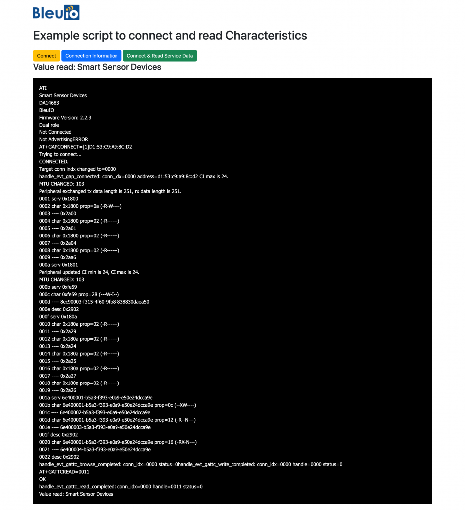
<h1 class="my-4">Example script to connect and read Characteristics</h1>
<button class="btn btn-warning" id="connect">Connect</button>
<button class="btn btn-primary" id="info">Connection Information</button>
<button class="btn btn-success" id="ReadService">
Connect & Read Service Data
</button>
<h3><div id="readResponse"></div></h3>
<div id="terminal"></div>
</div>
<script type="module" src="./script.js"></script>
</body>
</html>
Create a js page that contains the logic for connecting to dongle and then connect to Air quality monitoring BLE device HibouAir. After connecting to the device we try to read device manufacturing company name by reading characteristics. following is the script file.
As you can notice on the script we have a variable called device to connect. This is the mac address of the HibouAir BLE device that we are trying to connect. You can replace this mac address to your own device. After the connection we print out the response in a terminal. on the terminal we can see available service and characteristics. In this script we are trying to read device manufacturer name which is stored at 0011 handle. Therefore we pass the value as at_gattcread function. You can read more about the AT commands at BleuIO getting started guide.
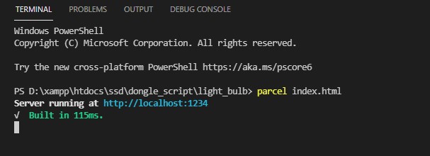
To run this script, we need a web bundler like parcel js.
Run the script with
npx parcel index.html
Example output
In this tutorial, we’ve successfully demonstrated how to connect to a BLE device using the BleuIO dongle and JavaScript. By leveraging the BleuIO’s Javascript library, we streamlined the process of establishing a connection, reading device characteristics, and displaying the information on a web page. BLE technology has vast potential for various applications, and BleuIO makes it easier than ever to interact with BLE devices programmatically. With this tutorial as a foundation, you can explore further and develop your own BLE-powered projects with confidence.
Bluetooth Low Energy (BLE) has become a popular technology for creating wireless communication between devices with low power consumption. When developing BLE applications, it’s essential to thoroughly test them to ensure they work correctly. This tutorial shows a basic test script that determines the role of a Bluetooth Low Energy (BLE) device and passes the test based on the device role. The test script utilizes the BleuIO Bluetooth Low Energy USB dongle along with a JavaScript Testing Framework. You can modify this script according to your specific needs for testing BLE applications.. We’ll communicate with the dongle using Node SerialPort, write AT commands, and read back responses from the dongle.
Prerequisites
Before we start, make sure you have the following:
Basic knowledge of JavaScript and testing concepts.
Setting Up the Environment
First, connect the BleuIO dongle to your computer. To find the path of the dongle, open your terminal and run the following command:
ls /dev/cu.*
Note down the path of the dongle (e.g., /dev/cu.usbmodem4048FDE6EBCB1).
Next, create a new directory for your project and initialize a Node.js project by running:
npm init -y
Now, install the required packages: SerialPort and Jest.
npm install serialport
npm install --save-dev jest
Writing the Role Check Function
Create a new file rolecheck.js and paste the following code:
import { SerialPort } from 'serialport';

const dongleReadWrite = () => {
  return new Promise((resolve) => {
    let readDataArray = [];
    const port = new SerialPort({
      path: '/dev/cu.usbmodem4048FDE6EBCB1', // Replace this with your dongle's path
      baudRate: 115200,
      dataBits: 8,
      parity: 'none',
      stopBits: 1,
    });

    // Function to write data to the dongle
    const writeData = async (cmd) => {
      port.on('open', () => {
        port.write(cmd + '\r\n', (err) => {
          if (err) {
            return console.log('Error writing data: ', err.message);
          }
        });
      });
    };

    // Function to read data from the dongle
    const readData = () => {
      return new Promise(function (resolve, reject) {
        port.on('readable', () => {
          let data = port.read();
          let enc = new TextDecoder();
          let arr = new Uint8Array(data);
          arr = enc.decode(arr);
          let removeRn = arr.replace(/\r?\n|\r/gm, '');
          if (removeRn != null) readDataArray.push(removeRn);
          return resolve(readDataArray);
        });
      });
    };

    // Write the command 'AT+GAPSTATUS' to the dongle
    writeData('AT+GAPSTATUS');

    // Read the response from the dongle after a delay of 1 second
    readData().then((data) => {
      setTimeout(() => {
        port.close();
        return resolve(data);
      }, 1000);
    });
  });
};

// Function to get the role of the dongle
export const getRole = () => {
  return new Promise((resolve) => {
    // Call dongleReadWrite() to fetch data from the dongle
    dongleReadWrite().then((data) => {
      const regex = /(Peripheral|Central)/i;
      // Find the role from the response data using regular expression
      const roleMatch = data.find((element) => regex.test(element));
      // Extract the role ('Peripheral' or 'Central') from the match
      const role = roleMatch ? roleMatch.match(regex)[0] : null;
      // Return the role to the caller
      return resolve(role);
    });
  });
};
The getRole() function connects to the dongle and writes the command AT+GAPSTATUS to find out the role. The response we get is an array, which looks like this [ ‘AT+GAPSTATUS’, ‘Peripheral roleNot ConnectedNot Advertising’ ] we extract the role information from it.
Writing the Test Script
Create another file rolecheck.test.js and paste the following code:
import { getRole } from './rolecheck';
import { jest } from '@jest/globals';
jest.useFakeTimers();

test('Get peripheral role', async () => {
  const dataPromise = getRole(); // Start the data fetching process

  jest.advanceTimersByTime(1000); // Advance the timer by 1 second

  // At this point, the timer has advanced by 1 second, but the data is not resolved yet
  // We can check that the dataPromise is still pending
  expect(dataPromise).toBeInstanceOf(Promise);

  jest.advanceTimersByTime(2000); // Advance the timer by another 2 seconds to complete the 3 seconds

  // Now, the data should be resolved, and the test should pass if the role is 'Peripheral'
  expect(dataPromise).resolves.toBe('Peripheral');
});
In the test script, we import the getRole() function from rolecheck.js. We use Jest’s fake timers to control the asynchronous flow and mimic the behavior of asynchronous code.
The test checks whether the role obtained from the getRole() function is 'Peripheral'. If it is, the test passes; otherwise, it fails.
Running the Test
To execute the test, run the following command in the terminal:
npm test
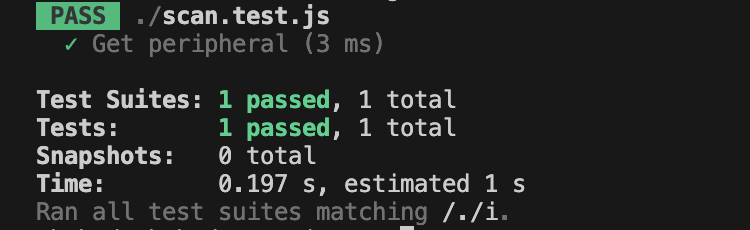
Jest will run the test, and you should see the test results on your terminal.
The response will look like this
Conclusion
In this tutorial, we explored how to communicate with the BleuIO dongle, write AT commands, and read back responses using a JavaScript Testing Framework (Jest). With the right testing approach, you can ensure the stability and correctness of your BLE application before deploying it to production. Happy testing!
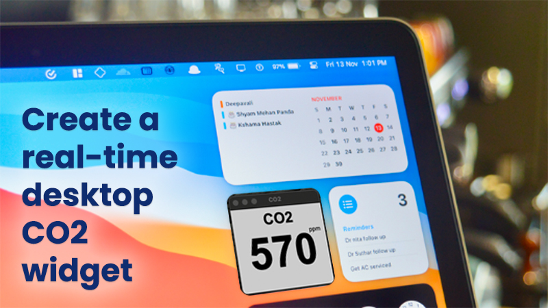
Creating a small real-time desktop CO2 widget using JavaScript and Bluetooth is a fun and engaging project that can help you understand how to work with Bluetooth communication and sensor data processing.
In this project we will use BleuIO to communicate with air quality monitoring sensor to read CO2 data. BleuIO is a bluetooth low energy usb dongle that helps to create BLE application easily. The AT command available on this device makes the development faster and easier.
There are many air quality sensor available but one popular choice is the HibouAir.
We will use electron js and node serial to connect with BleuIO. After that we will use AT commands to scan for nearby Bluetooth device that is advertising with a given board ID which is the air quality monitoring sensor.
Note: both BleuIO and HibouAir are available at digikey.
Here are the steps you can follow to create your own widget:
Hardware setup :
Connect BleuIO to the computer and wait for the device to recognize it. This usually takes 10 seconds. Connect the air quality monitoring sensor HibouAir to a power cable. Make sure the device is within 50 meters.
on terminal. This will install necessary libraries.
Inside this folder we will find three .js files and one html file. The index.html file is the frontend where we will see the real-time CO2 values.
The main.js file initialize the application and creates an window of 200px X 200px
render.js is the file which has all the logic go connect to BleuIO via serial port , gets real-time air quality data, decode it and finally print it on the screen.
Code explanation :
On render.js file, at first we make a list of devices connected to serial port. Then we filter out only the BleuIO devices by filtering with vendorID which is 2dcf. After that we pick the first item of the list.
Once we know the path of the BleuIO device , we connect to it.
ports = ports.filter((x) => x.vendorId == "2dcf");
      if (ports && ports.length > 0) {
        port = new SerialPort({
          path: ports[0].path,
          baudRate: 57600,
        });
}
Now that we are connected to the BleuIO dongle, we can write AT commands to it and get the response.
At first we write AT+DUAL to the dongle to put the dongle in dual role. So that we can scan for nearby devices and advertised data.
to put the dongle in dual role we write
port.write(Buffer.from("AT+DUAL\r"), function (err) {
          if (err) {
            document.getElementById("error").textContent =
              "Error writing at dual";
          } else {
            console.log('dongle in dual role')
}
In this project I am trying to get air quality data from a HibouAir device which has a board ID of 45840D. Therefore I look for advertised data that has this specific boardID. If i write AT+FINDSCANDATA=4584OD, BleuIO will filter out only advertise data from this board ID.
After writing this , we get a response from the dongle. To read the response from serial port we use
 port.on("readable", () => {
          let data = port.read();
console.log(data)
})
We can push the response in an array and later decide what to do with it.
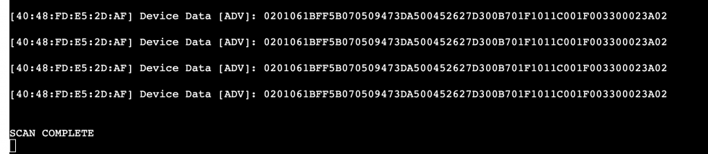
When we do a AT+FINDSCANDATA=45840D
the response from the dongle looks something like this
Then we take the last response by using
resp = readDataArray[readDataArray.length - 2];
After that , get the advertised data from the string by
resp.split(" ").pop();
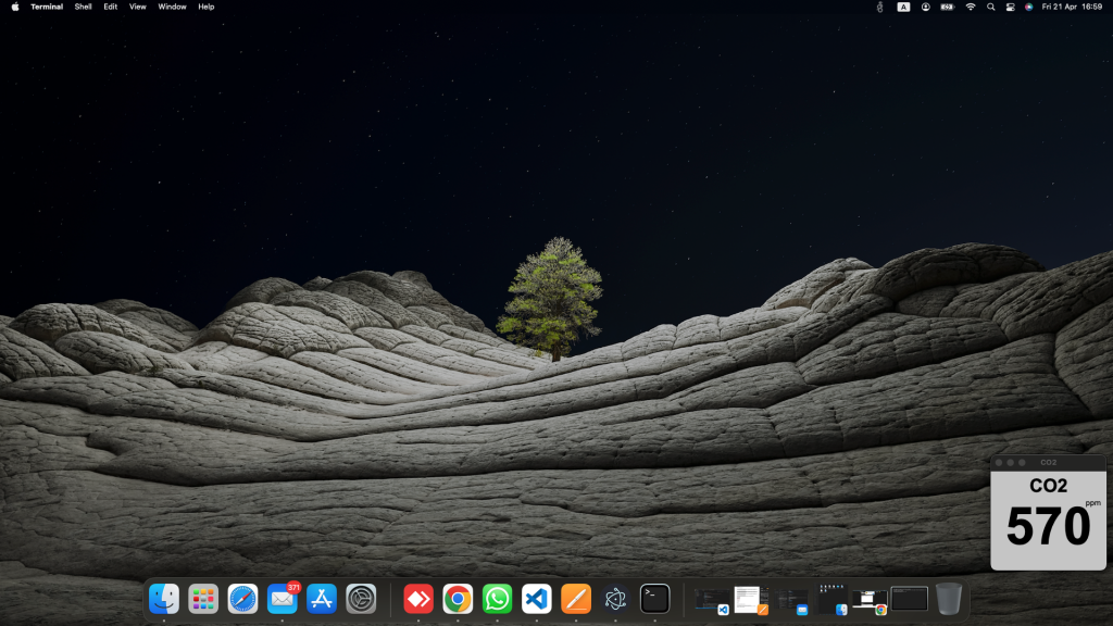
Now we have the advertised data in a variable. We can easily get the CO2 value from this string by selecting the position. The documentation from HibouAirs says , the CO2 value is right at the end of the string. In that case the value is 023A which is 570 is decimal.
We can print this value in our screen.
We can create a function that do the scanning every 20 seconds to get latest values.
Here is the complete code to render.js file
// This file is required by the index.html file and will
// be executed in the renderer process for that window.
// All of the Node.js APIs are available in this process.
const { SerialPort } = require("serialport");
var port;
var readDataArray = [];
async function listSerialPorts() {
  await SerialPort.list().then((ports, err) => {
    if (err) {
      document.getElementById("error").textContent = err.message;
      return;
    } else {
      document.getElementById("error").textContent = "";
    }
    console.log("ports", ports);

    if (ports.length === 0) {
      document.getElementById("error").textContent = "No ports discovered";
    } else {
      ports = ports.filter((x) => x.vendorId == "2dcf");
      if (ports && ports.length > 0) {
        port = new SerialPort({
          path: ports[0].path,
          baudRate: 57600,
        });
        port.write(Buffer.from("AT+DUAL\r"), function (err) {
          if (err) {
            document.getElementById("error").textContent =
              "Error writing at dual";
          } else {
            const myWriteFunc = () => {
              port.write(Buffer.from("AT+FINDSCANDATA=5B0705=3\r")),
                function (err) {
                  if (err) {
                    document.getElementById("error").textContent =
                      "Error writing findscandata";
                  } else {
                    console.log("here");
                  }
                };
            };
            myWriteFunc();
            setInterval(() => {
              myWriteFunc();
            }, 20000);
          }
        });
        // Read serial port data
        port.on("readable", () => {
          let data = port.read();
          let enc = new TextDecoder();
          let arr = new Uint8Array(data);
          let removeRn = enc.decode(arr).replace(/\r?\n|\r/gm, "");
          if (removeRn != null) readDataArray.push(removeRn);
          if (removeRn == "SCAN COMPLETE") {
            console.log(readDataArray);
            let resp = readDataArray[readDataArray.length - 2];

            let advData = resp.split(" ").pop();
            let pos = advData.indexOf("5B0705");
            console.log("advData", advData);
            console.log("c", advData.substr(pos + 46, 4));
            let co2 = parseInt("0x" + advData.substr(pos + 46, 4));
            console.log(co2);
            document.getElementById("co2Val").innerHTML = co2;
          }
        });
      } else {
        document.getElementById("error").innerHTML =
          "No device found. Please connect a BleuIO ongle to your computer and try again.";
      }
    }
  });
}

function listPorts() {
  listSerialPorts();
  setTimeout(listPorts, 20000);
}

// Set a timeout that will check for new serialPorts every 2 seconds.
// This timeout reschedules itself.
//setTimeout(listPorts, 2000);

listSerialPorts();
To build this app we need a library called electron-builder. To install this library we write on terminal npm i electron-builder
Once the library is build , we need to update our package json file and add build option or mac.
We will see a dmg file in our dist folder. Once we run the app, the widget will look like this.
The value will update every 20 seconds.
Creating a small desktop CO2 widget using JavaScript and BlueIO is a great way to learn about these technologies and create a useful tool for monitoring indoor air quality.
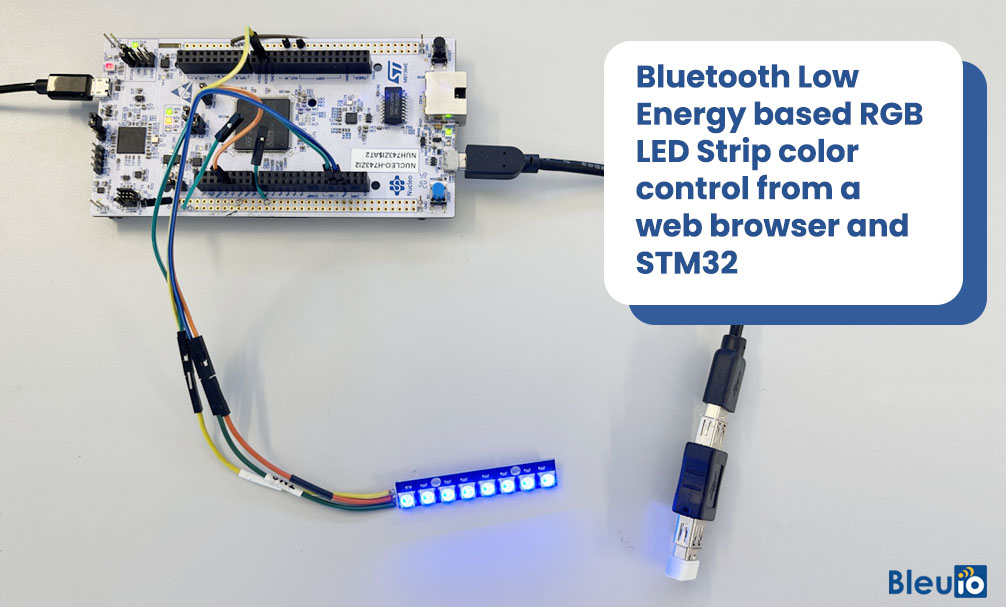
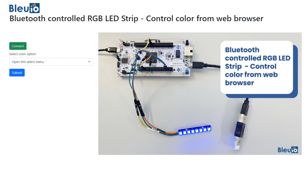
This project is about Bluetooth Low Energy based RGB LED Strip Color Control from a web browser and STM 32. The LEDs light strip can also be controlled wirelessly via a BLE scanning App using IOS or Android. With the received data, we decide which color of the RGB strip to activate.
You will need two dongles, one connected to the Nucleo board and one connected to a computer to control from web browser. The web script is also available on GitHub.
When the BleuIO Dongle is connected to the Nucleo boards USB port the STM32 will recognize it and directly start advertising. This allows the other Dongle to connect to it.
It will also accept 3 different inputs from the UART:
input
result
0
Send ATI (Request device information) command to BlueIO Dongle.
1
Manually turn the LED on
2
Manually turn the LED off
We have used a STM32 Nucleo-144 development board with STM32H743ZI MCU (STM32H743ZI micro mbed-Enabled Development Nucleo-144 series ARM® Cortex®-M7 MCU 32-Bit Embedded Evaluation Board) and the WS2812, a intelligent control LED light source, for this example.
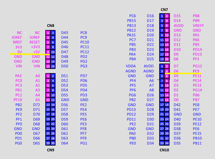
Connect the LED to the Nucleo Board by connecting:
4-7 VDC to 5V
GND to any GND
DIN to PE9
On the Nucleo NUCLEO-H743ZI2:
Note : If you want to use another setup you will have to make sure it support USB Host and beware that the GPIO setup might be different and may need to be reconfigured in the .ioc file.
This project is based on another STM32 project (https://github.com/smart-sensor-devices-ab/stm32_bleuio_example) with the interface to the WS2812 Interface WS2812 with STM32 by Controllers Tech
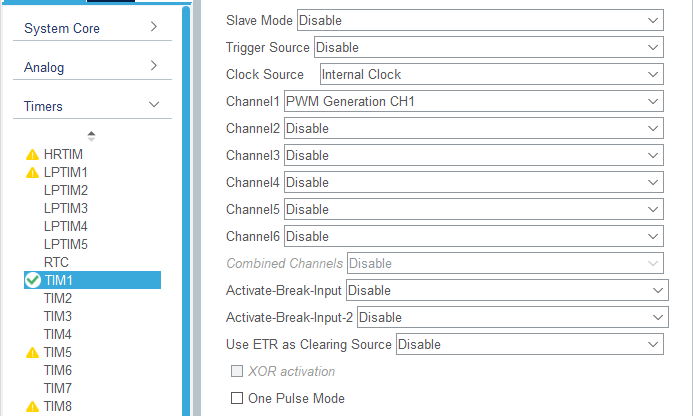
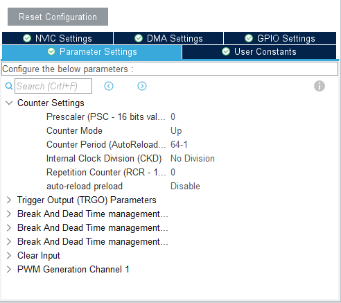
The DIN pin will be connected to TIM1 which need to be enabled in to the .ioc file:
Parameter Settings:
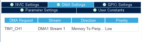
DMA for TIM1 will also be enabled:
In main.c we will need to add a callback for TIM PWM Pulse Finished:
Either clone the project, or download it as a zip file and unzip it, into your STM32CubeIDE workspace.
4.2 Importing as an Existing Project
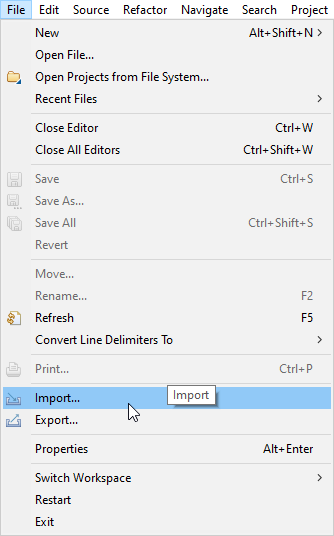
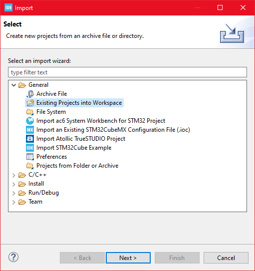
From STM32CubeIDE choose File>Import…
Then choose General>Existing Projects into Workspace then click ‘Next >’
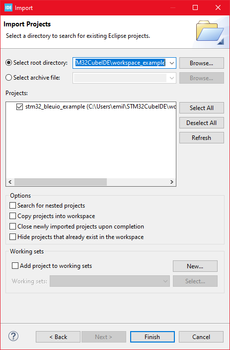
Make sure you’ve choosen your workspace in ‘Select root directory:’
You should see the project “stm32_bleuio_rgb_led_example”, check it and click ‘Finish’.
5. Running the example
In STMCubeIDE click the hammer icon to build the project.
Open up the ‘STMicroelectronics STLink Viritual COM Port’ with a serial terminal emulation program like TeraTerm, Putty or CoolTerm.
Serial port Setup:
Baudrate: 115200
Data Bits: 8
Parity: None
Stop Bits: 1
Flow Control: None
Connect the BleuIO Dongle before running the example
In STMCubeIDE click the green play button to flash and run it on your board. The first time you click it the ‘Run Configuration’ window will appear. You can just leave it as is and click run.
You should be greeted by this welcome message:
Welcome to STM32 BleuIO RGB LED Example!
Press 0 to run the ATI command
Press 1 to manually turn on LED
Press 2 to manually turn off LED
The LED will turn on briefly when starting up.
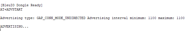
Wait until the message: “[BleuIO Dongle Ready]” is shown.
The LEDs should now turn off and you can now connect with the other dongle using the script.
You can also use the uart commands (0, 1 or 2):
Press 0 to get device information.
1 to turn on LED.
2 to turn off LED.
Dongle response will be printed to UART.
Control the colors from a web browser
Connect the BleuIO dongle to the computer. Run the web script to connect to the other BleuIO dongle on the STM32. The web script is available inside the source file. Now we can control the colors wirelessly.
Create a simple Html file called index.html which will serve as the frontend of the script. This Html file contains some buttons that help connect and read advertised data from the remote dongle, which is connected to stm32.
<!DOCTYPE html>
<html lang="en">
  <head>
    <meta charset="UTF-8" />
    <meta http-equiv="X-UA-Compatible" content="IE=edge" />
    <meta name="viewport" content="width=device-width, initial-scale=1.0" />
    <link
      href="https://cdn.jsdelivr.net/npm/bootstrap@5.1.3/dist/css/bootstrap.min.css"
      rel="stylesheet"
      integrity="sha384-1BmE4kWBq78iYhFldvKuhfTAU6auU8tT94WrHftjDbrCEXSU1oBoqyl2QvZ6jIW3"
      crossorigin="anonymous"
    />
    <title>
      Bluetooth controlled RGB LED Strip - Control color from web browser
    </title>
  </head>
  <body class="mt-5">
    <div class="container mt-5">
      <img
        src="https://www.bleuio.com/blog/wp-content/themes/bleuio/images/logo.png"
      />
      <h1 class="mb-5">
        Bluetooth controlled RGB LED Strip - Control color from web browser
      </h1>

      <div class="row">
        <div class="col-md-4 pt-5">
          <button class="btn btn-success mb-2" id="connect">Connect</button>
          <form method="post" id="sendMsgForm" name="sendMsgForm">
            <div class="mb-3">
              <label for="msgToSend" class="form-label"
                >Select color option</label
              >
              <select
                class="form-select"
                aria-label="Default select example"
                name="msgToSend"
                id="msgToSend"
                required
              >
                <option selected>Open this select menu</option>
                <option value="L=0">LED Off</option>
                <option value="L=1">LED On</option>
                <option value="L=RED">Set LED lights red</option>
                <option value="L=GREEN">Set LED lights green</option>
                <option value="L=BLUE">Set LED lights blue</option>
                <option value="L=RAINBOW">
                  Set LEDs lights to different colors
                </option>
              </select>
            </div>

            <button type="submit" class="btn btn-primary">Submit</button>
          </form>
        </div>
        <div class="col-md-8">
          <img
            src="https://www.bleuio.com/blog/wp-content/uploads/2022/09/bluetooth-controlled-rgb-led-strip-collor-control.jpg"
          />
        </div>
      </div>
    </div>

    <script src="script.js"></script>
  </body>
</html>
Create a js file called script.js and include it at the bottom of the Html file. This js file uses the BleuIO js library to write AT commands and communicate with the other dongle.
import * as my_dongle from 'bleuio'
const dongleToConnect='[0]40:48:FD:E5:2F:17'
document.getElementById('connect').addEventListener('click', function(){
  my_dongle.at_connect()
  document.getElementById("connect").disabled=true;
  document.getElementById("sendMsgForm").hidden=false;
})

document.getElementById("sendMsgForm").addEventListener("submit", function(event){
    event.preventDefault()


    my_dongle.ati().then((data)=>{
        //make central if not
        if(JSON.stringify(data).includes("Peripheral")){
            console.log('peripheral')
            my_dongle.at_central().then((x)=>{
                console.log('central now')
            })
        }
    })
    .then(()=>{
        // connect to dongle
        my_dongle.at_getconn().then((y)=>{
            if(JSON.stringify(y).includes(dongleToConnect)){
                console.log('already connected')
            }else{
                my_dongle.at_gapconnect(dongleToConnect).then(()=>{
                    console.log('connected successfully')
                })
            }
        })
        .then(()=>{
            var theVal = document.getElementById('msgToSend').value;
            console.log('Message Send  '+theVal)
            // send command to show data
            my_dongle.at_spssend(theVal).then(()=>{
                console.log('Message Send '+theVal)
            })
        })

    })
  });
The script has a button to connect to COM port on the computer. After connecting to the dongle , we should be able to control the colors of the LED strip.
To connect to the BleuIO dongle on the STM32, make sure the STM32 is powered up and a BleuIO dongle is connected to it.
Get the MAC address
Follow the steps to get the MAC address of the dongle that is connected to STM32
- Open this site https://bleuio.com/web_terminal.html and click connect to dongle.
- Select the appropriate port to connect.
- Once it says connected, type ATI. This will show dongle information and current status.
- If the dongle is on peripheral role, set it to central by typing AT+CENTRAL
- Now do a gap scan by typing AT+GAPSCAN
- Once you see your dongle on the list ,stop the scan by pressing control+c
- Copy the ID and paste it into the script (script.js) line #2
Run the web script
You will need a web bundler. You can use parcel.js
Once parcel js installed, go to the root directory of web script and type “parcel index.html”. This will start your development environment.
Open the script on a browser. For this example we opened http://localhost:1234
You can easily connect to the dongle and update the LED strip.
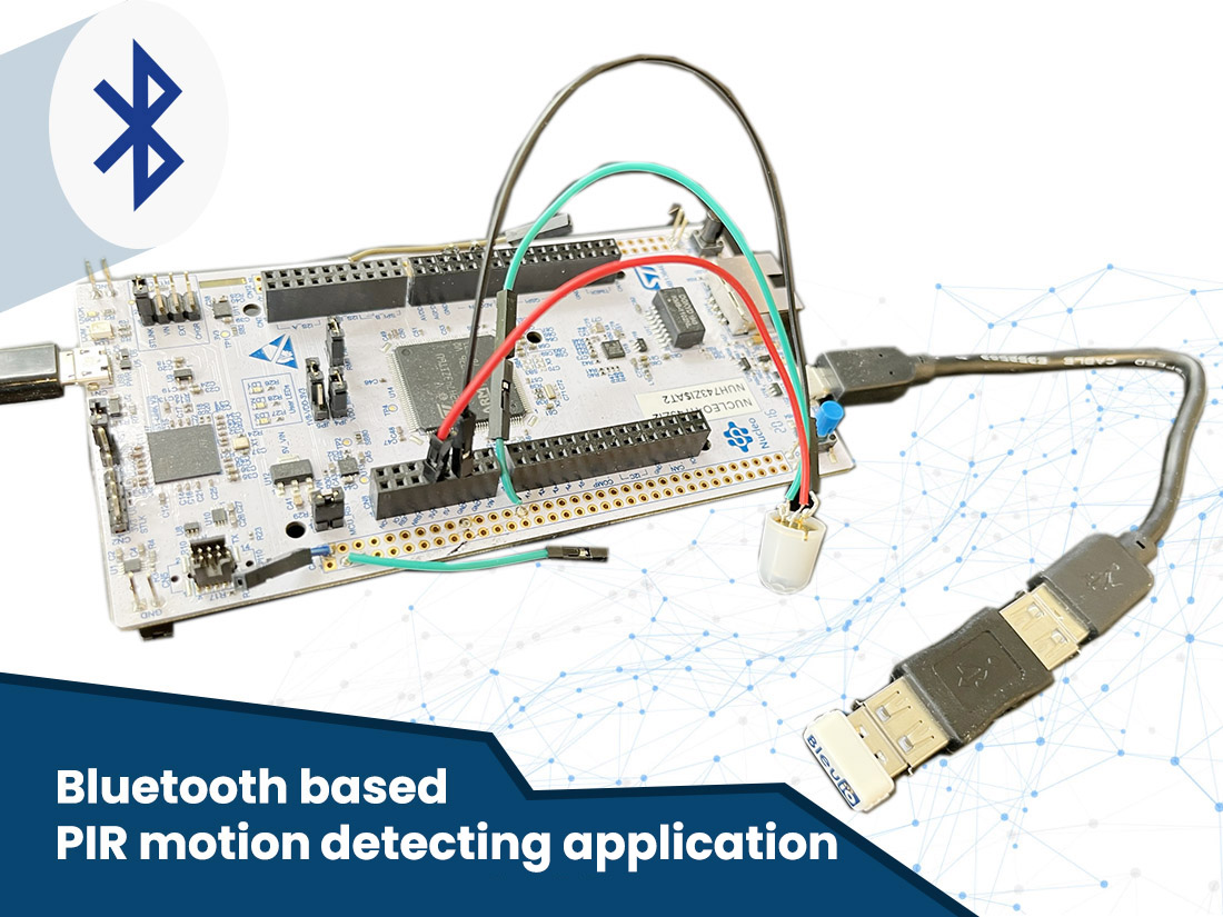
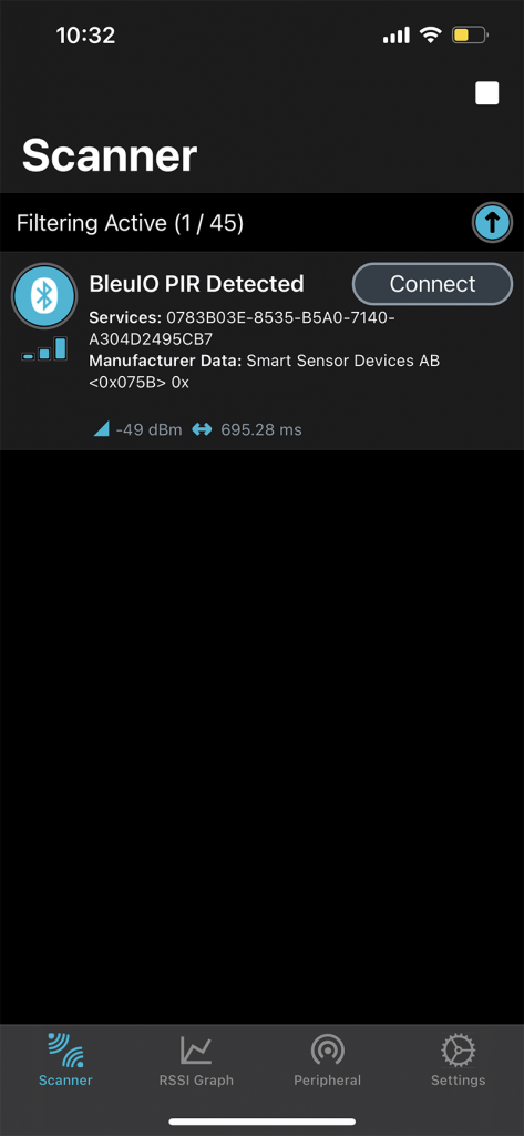
In this project we will use a PIR sensor to detect motion. Once motion is detected, it will trigger an interrupt and the BleuIO dongle connected to the board will advertise for 25 seconds. You can expand the project based on your needs further.
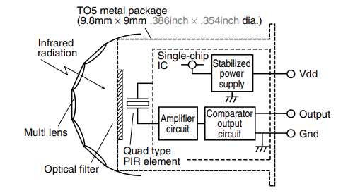
A PIR (passive infrared) Sensor is an electronic device that detects heats from human or animal body, giving a detection signal when movement happens in a given area or range of the sensor.
For this project, we will need one dongle and a PIR sensor (for example: https://www.digikey.com/short/4v12z2nw). When the BleuIO Dongle is connected to the Nucleo boards USB port the STM32 will recognize it and set up a new device name for the dongle: BleuIO PIR Detected. This will show up when the dongle is advertising.
Either clone the project, or download it as a zip file and unzip it, into your STM32CubeIDE workspace.
2.2 Importing as an Existing Project
From STM32CubeIDE choose File>Import…
Then choose General>Existing Projects into Workspace then click ‘Next >’
Make sure you’ve choosen your workspace in ‘Select root directory:’
You should see the project “stm32_bleuio_pir_example”, check it and click ‘Finish’.
If you download the project as a zip file you will need to rename the project folder from ‘stm32_bleuio_pir_example-master’ to ‘stm32_bleuio_pir_example’
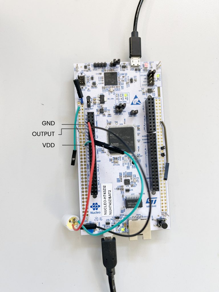
5. Connecting the sensor
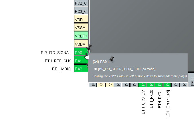
Connect the PIR Sensor Gnd to ground and Vdd to power and Output to a pin of your choice on the Nucleo board (In the example we use PA0)
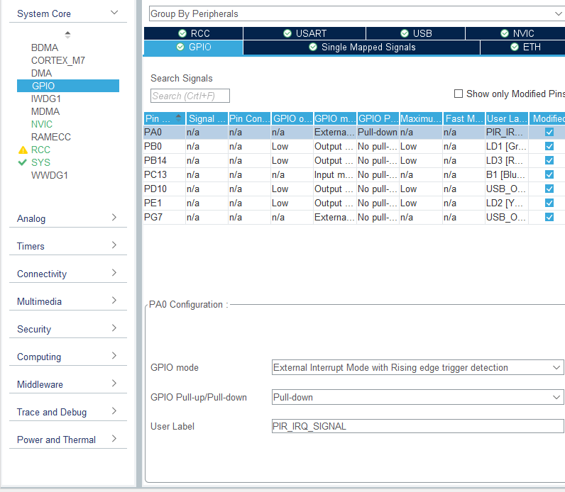
If you want a different PIN you will need to go into the STM32Cube ioc file and make some edits:
Click on PA0 and select Reset_State in the STM32Cube ioc file.
Click on your desired Pin and select EXTIO
Then go to GPIO under System Core and make sure you setup the pin as follows:
GPIO mode: External Interrupt Mode with Rising edge trigger detection
GPIO Pull-up/Pull-down: Pull-down
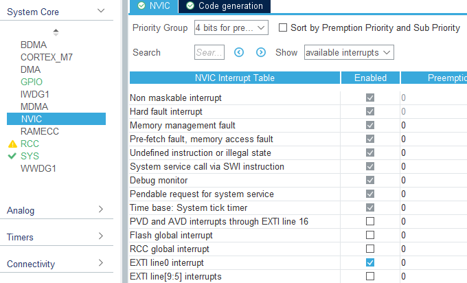
Then go to NVIC under System Core and make sure EXTI line0 interrupt is enabled
6. Running the example
In STMCubeIDE click the hammer icon to build the project.
Open up the ‘STMicroelectronics STLink Viritual COM Port’ with a serial terminal emulation program like TeraTerm, Putty or CoolTerm.
Baudrate: 115200
Data Bits: 8
Parity: None
Stop Bits: 1
Flow Control: None
In STMCubeIDE click the green play button to flash and run it on your board. The first time you click it the ‘Run Configuration’ window will appear. You can just leave it as is and click run.
Connect the BleuIO Dongle.
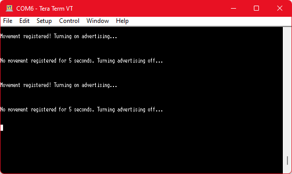
7. Output
When the PIR sensor detects movement it will trigger an interrupt that in turn will tell the BleuIO Dongle to advertise for 25 seconds. Just so the PIR Sensor will not trigger constantly we have put a 20 second timeout before it will trigger again. If no new interrupts have been detected after the 25 second advertising timer has run out the BleuIO Dongle will stop advertising and wait for a new interrupt to happen.
The yellow LED on the STM32 board also toggles if there is a movement.
A beacon is a Bluetooth Low Energy (BLE) transmitter, a “Thing” that is often talked about on the Internet of Things. The information can be received by devices with a Bluetooth connection (smartphones, computers, tablets or industrial gateways among others).
One of the biggest advantages of this wireless communication protocol, BLE, is its low energy consumption, which gives these beacons a long battery life.
Who uses beacons?
Beacons have so far and primarily been used in retail to attract customers to a loyal behaviour, by collecting points or by sending them a promotional offer, the customer experience can be improved. This type of connected object has been used for many years in a varied number of industries and the industry is really starting to adopt the technology.
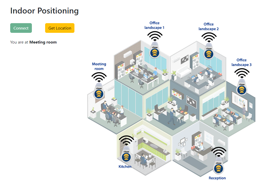
Indoor positioning
There are many use cases for Bluetooth Beacons. This article discusses the indoor positioning system.
There are many reasons an individual or organisation would be interested in indoor positioning. From improving the ease of navigation, finding what you’re looking for, delivering/receiving targeted location-based information, improving accessibility, accruing valuable data insights and much more.
Bluetooth Low Energy (BLE) signals from battery-driven beacons are at the soul of indoor location technology. It’s one of the most recognised technologies that has appeared for indoor positioning and has become industry-standard available recently. It uses BLE beacons (or iBeacons) that are affordable, small, has a long battery life, and do not need an external energy source. The device (smartphone/ watch etc.) detects the signal from the beacon and can approximately calculate the distance to the beacon, therefore calculating a user’s indoor location.
A script on BLE beacons based indoor positioning system
Many manufacturers make compatible BLE Beacons because BLE is an open industry standard. Manufacturers do vary in terms of quality, battery life, signal stability, and how they package the beacons. For this Indoor positioning example project, we are going to use Close Beacon to determine users location.
Instructions
At first, we place Close Beacon in different rooms and note their mac address.
When we do a GAP SCAN, we will notice the close beacons on the list along with other devices.
We filter out the close beacons and sort them by RSSI.
We pick the first device from the list and match it with the MAC address
Finally, we print out the name of the location of Close Beacon.
Create a js file that communicates with the dongle and processes the response to determine the user’s current location.
import * as my_dongle from 'bleuio'
document.getElementById('connect').addEventListener('click', function(){
  my_dongle.at_connect()
  document.getElementById('checkLocation').removeAttribute("disabled");

})
//List of Close Beacons and their name based on mac address
let beaconArray={
  "Conference Room":"[D0:76:50:80:00:3A]",
  "Entrance":"[D0:76:50:80:00:97]",
  "SSD lab":"[D0:76:50:80:0B:9D]",
  "IAD lab":"[D0:76:50:80:0F:49]",
  "Office":"[D0:76:50:80:02:30]",
}
document.getElementById('checkLocation').addEventListener('click', function(){
  document.getElementById("loading").style.display = "block";
  document.getElementById('connect').setAttribute("disabled","");
// put the dongle on central role ,so that we can scan
  my_dongle.at_central().then(()=>{
    //enable rssi for the scan response
    my_dongle.at_showrssi(1).then(()=>{
      //filter advertised data , so it only shows close beacon on the response
      my_dongle.at_findscandata('9636C6F7',6).then((data)=>{
        //convert array string to array of object with key value
        const formated = data.map((item) => {
          if(item.length>30){
            const splitted= item.split(' ');
            let mac=splitted[2]
            let rssi=splitted[1]
            return { mac,rssi};
          }
        });
         //sort based on rssi value
        formated.sort((a, b) => parseInt(b.rssi) > parseInt(a.rssi) && 1 || -1)
        // get the name of the close beacon by mac address
        let locationName=Object.keys(beaconArray).find(key => beaconArray[key] === formated[0]['mac']);
        document.getElementById("loading").style.display = "none";
        // print out the location
        document.getElementById("theLocation").innerHTML = "You are at <strong>"+locationName+"</strong";
      })
    })
  })
})
Python has a lot of GUI frameworks, but Tkinter is the only framework that’s built into the Python standard library. Tkinter has several strengths. It’s cross-platform, so the same code works on Windows, macOS, and Linux. Visual elements are rendered using native operating system elements, so applications built with Tkinter look like they belong on the platform where they’re run.
Tkinter is lightweight and relatively painless to use compared to other frameworks. This makes it a compelling choice for building GUI applications in Python, especially for applications where a modern sheen is unnecessary, and the top priority is to quickly build something functional and cross-platform.
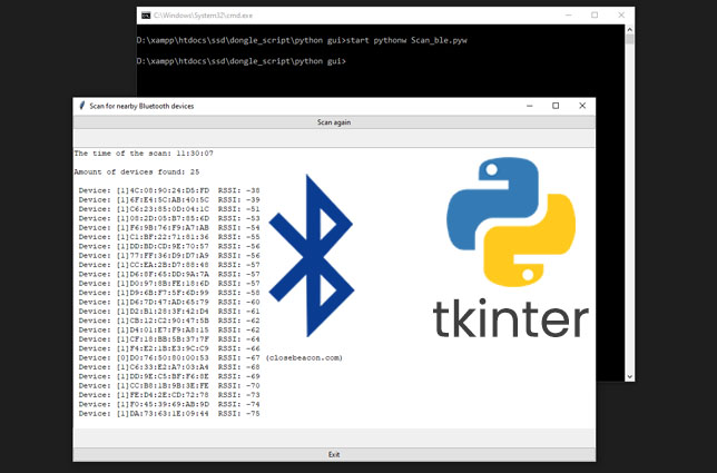
In this article, we will try to create a simple Python GUI application that can scan for nearby Bluetooth devices using Pyserial and shows the list on the screen.
Connect the BleuIO to your computer. The script uses pyserial to connect to the Bluetooth USB dongle BleuIO.
Update the script and write the correct COM port (line 25), where the dongle is connected.
After connecting to the dongle, we put the dongle into the central role using AT+CENTRAL so that it can scan for nearby Bluetooth devices.
Then we do a simple Gap scan using AT+GAPSCAN=3 command to scan for nearby Bluetooth devices for 3 seconds.
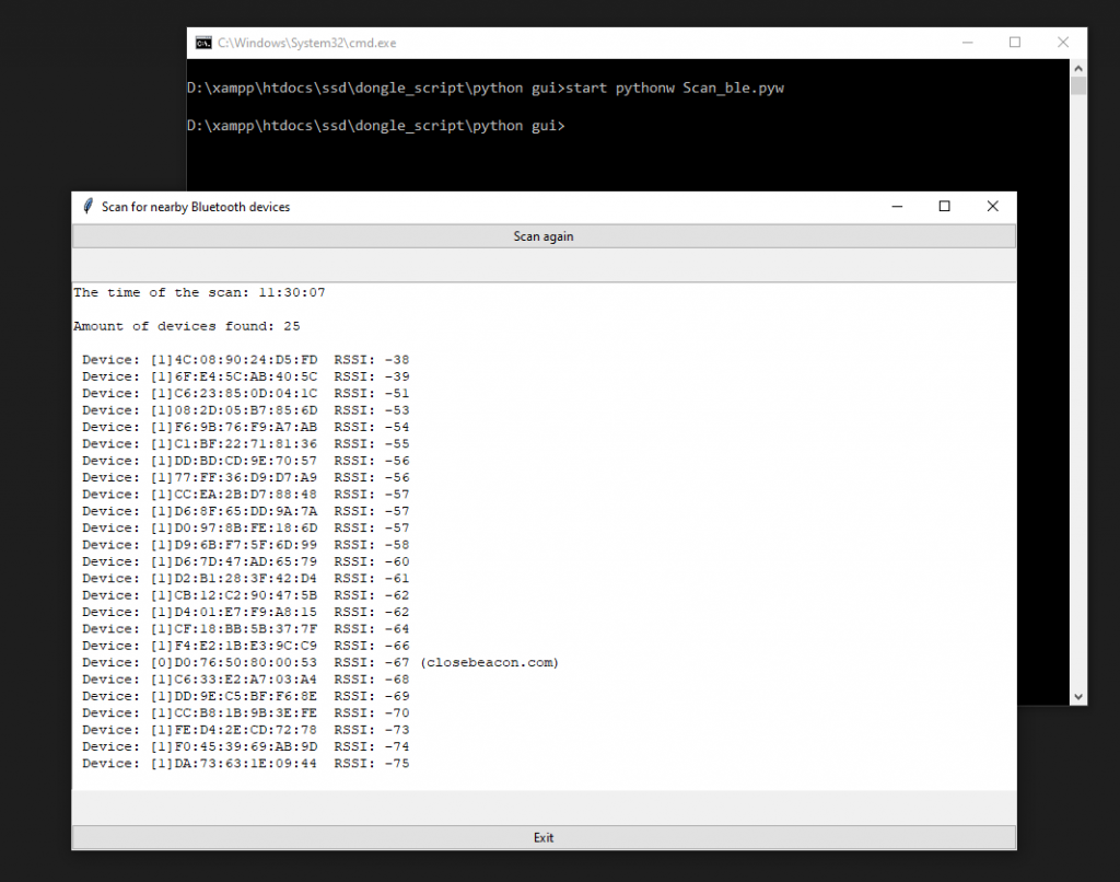
After that, we read the output from the serial port and filter the device to get the unique number of devices.
Then we add a timestamp when the scan was completed.
Finally, we sort the result by RSSI value before printing it out on screen.
‘Scan again’ button will do the whole process again.
Here is the final script file.
# Gjort av William
# 2022-06-16
# Smart Sensors Devices AB
#
# libraries that is necessary for tkinter to work
import tkinter as tk
from tkinter import  ttk

# this is imported for the dongle and also for the "time.sleep()" commands
import serial
import time

# this is the library that is uesd to check the current time
import datetime
now = datetime.datetime.now()

# this is what creates the main window
main_window = tk.Tk()

#changes the titel of the window
main_window.title('Scan for nearby Bluetooth devices')


# sets your port for the dongle
your_com_port = "COM18"
connecting_to_dongle = True

#changes the size of the screens window
window_width = 900
window_height = 500

# get the screen dimension
screen_width = main_window.winfo_screenwidth()
screen_height = main_window.winfo_screenheight()
# find the center point
center_x = int(screen_width/2 - window_width / 2)
center_y = int(screen_height/2 - window_height / 2)
# set the position of the window to the center of the screen
main_window.geometry(f'{window_width}x{window_height}+{center_x}+{center_y}')

# apply the grid layout
main_window.grid_columnconfigure(1, weight=1)
main_window.grid_rowconfigure(1, weight=1)


# create the text widget
text = tk.Text(main_window, height=30, width=30)
text.grid(row=1, column=1, sticky=tk.EW)


# this is the part of the code that communicates whit the dongle
print("Connecting to dongle...")
while connecting_to_dongle:
    try:
        console = serial.Serial(
            port=your_com_port,
            baudrate=57600,
            parity="N",
            stopbits=1,
            bytesize=8,
            timeout=0,
        )
        if console.is_open.__bool__():
            connecting_to_dongle = False
    except:
        print("Dongle not connected. Please reconnect Dongle.")
        time.sleep(5)
print("Connected to Dongle.")

console.write(str.encode("AT+CENTRAL"))
console.write("\r".encode())
print("Putting dongle in Central role.")
time.sleep(0.1)

console.write(str.encode("AT+GAPSCAN=3"))
console.write("\r".encode())
time.sleep(0.1)
print("Looking for nearby Bluetooth devices ...")
dongle_output2 = console.read(console.in_waiting)
time.sleep(3)
print("Scan Complete!")
filtered = []

for dev in dongle_output2.decode().splitlines():
    if len(dev)>20:
        filtered.append(dev.split(maxsplit=1)[1])

seen = set()
out = []
for elem in filtered:
    prefix = elem.split(' ')[1]
    if prefix not in seen:
        seen.add(prefix)
        out.append(elem)

# sort list
out.sort(key=lambda x:int(x.split()[3]), reverse=True)

# writes out the amount of bluetooth devices found on the main screen
text.insert('0.5', 'Amount of devices found: ' + str(len(out)) + '\n\n')

# funktion to get the current time
def get_time():
    return now.strftime('%H:%M:%S')

# prints out the time of the scan on the main screen
text.insert('1.0','The time of the scan: ' + str(get_time()) + '\n\n')

# writes out the results on the main screen
for i in range(0,len(out)):
    position = f'{i+5}.{len(out[i])}'
    tempStr = out[i] + "\n"
    text.insert(position,f' {tempStr}')

# is supposed to delet everyting on the list
out.clear()

#the funktion for the scan button
def button_clicked():
    # enables the programe to change the results on the main screen to the new ones after the user presses the scan button
    text['state'] = 'normal'
    # update the current time.
    now = datetime.datetime.now()
    # funktion to get the current time
    def get_time():
        return now.strftime('%H:%M:%S')
    # this simply puts a emty row betwen the results and the rest of the output on kommandotolken
    print()
    # this delets the previous output that is on the main screen
    text.delete('0.0', tk.END)

    # this is the part of the code that communicates whit the dongle
    console.write(str.encode("AT+GAPSCAN=3"))
    console.write("\r".encode())
    time.sleep(0.1)

    dongle_output2 = console.read(console.in_waiting)
    time.sleep(3)
    filtered = []

    for dev in dongle_output2.decode().splitlines():
        if len(dev)>20:
            filtered.append(dev.split(maxsplit=1)[1])

    seen = set()
    out = []
    for elem in filtered:
        prefix = elem.split(' ')[1]
        if prefix not in seen:
            seen.add(prefix)
            out.append(elem)

    # sort list
    out.sort(key=lambda x:int(x.split()[3]), reverse=True)


    #writes out the time of the scan on the main screen
    text.insert('1.0','The time of the scan: ' + str(get_time()) + '\n\n')

     # writes out the amount of bluetooth devices found on the main screen
    text.insert('0.0', 'Amount of devices found: ' + str(len(out)) + '\n\n')

    # writes out the results on the main screen
    for i in range(0,len(out)):
        position = f'{i+5}.{len(out[i])}'
        tempStr = out[i] + "\n"
        text.insert(position,f' {tempStr}')

    # makes it so that you cant edite the results on the main screen
    text['state'] = 'disabled'

#what calls the function for the scan button. also fixes what the user will see as the buttons name.
main_button = ttk.Button(
    main_window,
    text='Scan again',
    command=lambda: button_clicked()
)
# creat the scan button
main_button.grid(row=0, column=1, sticky=tk.EW)

# just an exit button.
exit_button = ttk.Button(
    main_window,
    text='Exit',
    command=lambda: main_window.quit()
)
# this determens were the exit button is located
exit_button.grid(row=2, column=1, sticky=tk.EW)

# makes it so that you cant edite the results on the main screen
text['state'] = 'disabled'

# keeps the main window open
main_window.mainloop()

time.sleep(1)
console.close()
Source code is available at https://github.com/smart-sensor-devices-ab/python_gui_tkinter_bluetooth.git
Run the script
To run the script we use start
pythonw Scan_ble.pyw
Note : Scan_ble.pyw is the file name
Output
After running the script, we see a total 25 devices found nearby. We can scan again using the ‘Scan again’ button