Smart Sensor Devices AB, a manufacturer and provider of IoT solutions, is pleased to announce that its Bluetooth low energy USB dongle called BleuIO will be available for immediate shipment worldwide through the Robotshop Marketplace.
The product is listed on RobotShop and available for purchase.
“Joining the RobotShop Marketplace is a strategic move that allows our Bluetooth Low Energy USB dongle BlueIO to be viewed and purchased with ease through RobotShop’s well established online process. Products will ship typically within 2 days of order placement from Smart Sensor Devices, Stockholm, Sweden. It’s a winning combination for Smart Sensor Devices, and we look forward to working with RobotShop.” said Axel G. Hammar, Founder & CEO, Smart Sensor Devices.
About BleuIO
This BleuIO is a Bluetooth low energy USB dongle that can create a new BLE 5.0 application in the fastest and easiest way. Just use the AT Commands available on the device. Details about the AT commands can be found on the getting started guide, which will help anyone make a fast peripheral or central application (or both) without developing a single line of embedded code.
It is a fully integrated solution, providing MCU and Bluetooth radio in one chip, based on Dialog Semiconductor latest Bluetooth chip DA14683. The FLASH based device permits field or boot upgradable, while the application is stored on FLASH memory. Custom settings can also be stored on FLASH memory or OTP for higher integrity. It supports Windows 10, Linux and macOS.
About Smart Sensor Devices
Smart Sensor Devices is a Swedish company working globally with the latest IoT solutions. We are located in Stockholm, the hottest hub for IoT inventions. Get in contact with us today and explore how you can become part of it! Our long-term experience in IoT devices and systems is crucial for giving your business the most for your investments, improving Time To Market, and lowering your risk.
About RobotShop
RobotShop operates globally and specializes in robotics technology. They offer a wide range of products and services in this sector. Since its founding in 2003, RobotShop is renowned as the most visited robotics website in the world, offering a variety of robotic goods, such as educational and professional robots, as well as mechanical and electronic parts and components. Apart from that, RobotShop’s website brings a large number of visitors. Its audience includes amateurs and professionals with a keen interest in emerging technologies, businesses, the education sector, as well as a large community promoting communication, mutual aid and technical support.
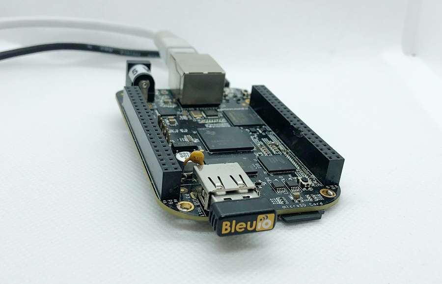
This is a simple example showcasing how to control a BleuIO dongle connected to Beaglebone Black using a python script.
When running the script, it will first ask for the com port where the dongle is connected (usually ‘/dev/ttyACM0’). After that, the BleuIO will start advertising. Every 8th second it will turn on one of the onboard Beaglebone Black LEDs whilst changing the BLE advertising name to indicate which LED is on.
We are using the Adafruit_BBIO python library that comes with the Beaglebone to control the onboard LEDs. First we define the LEDs names and then set them as GPIO Outputs. Then we define the advertising messages that the BleuIO will switch between. Lets break one down:
“10” is the size of the advertising packet in HEX. “09” is the flag for device name (Complete Local Name). “42:6C:65:75:49:4F:20:4C:45:44:20:30:20:4F:4E” is the packet itself, translated from HEX to ASCII it says: “BleuIO LED 0 ON”
Afterwards the user is presented with a message to input the com port the BleuIO is connected to. If you are not using a USB Hub the port should be ‘/dev/ttyACM0’.
You can change the comport name in the Python script and fill in your COM port.
com_input = "/dev/ttyACM0"
The script continues into the main loop, where it will first make sure all LEDs are off and then start BLE advertising.
The loop iterates through all four LEDs. In every iteration it turns one LED on and advertise the LED name then continue to the next LED. This will continue until the script is aborted.
import serial
import time
import Adafruit_BBIO.GPIO as GPIO


LED_USR0 = "USR0"
LED_USR1 = "USR1"
LED_USR2 = "USR2"
LED_USR3 = "USR3"

GPIO.setup(LED_USR0, GPIO.OUT)
GPIO.setup(LED_USR1, GPIO.OUT)
GPIO.setup(LED_USR2, GPIO.OUT)
GPIO.setup(LED_USR3, GPIO.OUT)

LED0_ON_ADV_MSG = "10:09:42:6C:65:75:49:4F:20:4C:45:44:20:30:20:4F:4E:"
LED1_ON_ADV_MSG = "10:09:42:6C:65:75:49:4F:20:4C:45:44:20:31:20:4F:4E:"
LED2_ON_ADV_MSG = "10:09:42:6C:65:75:49:4F:20:4C:45:44:20:32:20:4F:4E:"
LED3_ON_ADV_MSG = "10:09:42:6C:65:75:49:4F:20:4C:45:44:20:33:20:4F:4E:"

# Turn off all LEDs
GPIO.output(LED_USR0, GPIO.LOW)
time.sleep(0.1)
GPIO.output(LED_USR1, GPIO.LOW)
time.sleep(0.1)
GPIO.output(LED_USR2, GPIO.LOW)
time.sleep(0.1)
GPIO.output(LED_USR3, GPIO.LOW)
time.sleep(0.1)

print("\nBlueIO BeagleBone Example!\n\n")
connecting_to_dongle = 0
com_input = ""

start_input = 0
valid_input = 0
while start_input == 0:
    com_input = input(
        "Enter Com port of Dongle (default for BeagleBone: '/dev/ttyACM0'):\n>>"
    )
    print("\nComport to use: " + com_input)
    input_continue = input(
        "If your happy with your choice just press Enter to continue the script. Else type E to exit or R to redo your choice. \n>>"
    )
    if input_continue.upper() == "E":
        start_input = 1
    elif input_continue.upper() == "":
        start_input = 1
    elif input_continue.upper() == "R":
        valid_input = 0
        start_input = 0
if input_continue.upper() == "E":
    print("Exiting script...")
    exit()

console = None

while 1:
    try:
        print("Please wait...")
        time.sleep(0.5)
        console.write(str.encode("AT+DUAL"))
        console.write("\r".encode())
        time.sleep(0.5)
        print("Starting Advertising...")
        console.write(str.encode("AT+ADVSTART"))
        console.write("\r".encode())
        time.sleep(0.5)
        led_turn = 0
        # Turn off all LEDs
        GPIO.output(LED_USR0, GPIO.LOW)
        time.sleep(0.1)
        GPIO.output(LED_USR1, GPIO.LOW)
        time.sleep(0.1)
        GPIO.output(LED_USR2, GPIO.LOW)
        time.sleep(0.1)
        GPIO.output(LED_USR3, GPIO.LOW)
        time.sleep(0.1)
        while True:
            if led_turn == 0:
                print("\nTurning LED USR0 ON")
                console.write(str.encode("AT+ADVRESP="))
                console.write(LED0_ON_ADV_MSG.encode())
                console.write("\r".encode())
                GPIO.output(LED_USR0, GPIO.HIGH)
                GPIO.output(LED_USR1, GPIO.LOW)
                GPIO.output(LED_USR2, GPIO.LOW)
                GPIO.output(LED_USR3, GPIO.LOW)
                led_turn = led_turn + 1
            elif led_turn == 1:
                print("\nTurning LED USR1 ON")
                console.write(str.encode("AT+ADVRESP="))
                console.write(LED1_ON_ADV_MSG.encode())
                console.write("\r".encode())
                GPIO.output(LED_USR0, GPIO.LOW)
                GPIO.output(LED_USR1, GPIO.HIGH)
                GPIO.output(LED_USR2, GPIO.LOW)
                GPIO.output(LED_USR3, GPIO.LOW)
                led_turn = led_turn + 1
            elif led_turn == 2:
                print("\nTurning LED USR2 ON")
                console.write(str.encode("AT+ADVRESP="))
                console.write(LED2_ON_ADV_MSG.encode())
                console.write("\r".encode())
                GPIO.output(LED_USR0, GPIO.LOW)
                GPIO.output(LED_USR1, GPIO.LOW)
                GPIO.output(LED_USR2, GPIO.HIGH)
                GPIO.output(LED_USR3, GPIO.LOW)
                led_turn = led_turn + 1
            elif led_turn == 3:
                print("\nTurning LED USR3 ON")
                console.write(str.encode("AT+ADVRESP="))
                console.write(LED3_ON_ADV_MSG.encode())
                console.write("\r".encode())
                GPIO.output(LED_USR0, GPIO.LOW)
                GPIO.output(LED_USR1, GPIO.LOW)
                GPIO.output(LED_USR2, GPIO.LOW)
                GPIO.output(LED_USR3, GPIO.HIGH)
                led_turn = 0

            time.sleep(8)

    except KeyboardInterrupt:
        GPIO.output(LED_USR0, GPIO.LOW)
        time.sleep(0.1)
        GPIO.output(LED_USR1, GPIO.LOW)
        time.sleep(0.1)
        GPIO.output(LED_USR2, GPIO.LOW)
        time.sleep(0.1)
        GPIO.output(LED_USR3, GPIO.LOW)
        time.sleep(0.1)
        print("Exiting script...")
        exit()
    except:
        print("\n\nDongle not connected.\n")
        connecting_to_dongle = 0
        while connecting_to_dongle == 0:
            try:
                print("Trying to connect to dongle...")
                console = serial.Serial(
                    port=com_input,
                    baudrate=57600,
                    parity="N",
                    stopbits=1,
                    bytesize=8,
                    timeout=0,
                )
                if console.is_open.__bool__():
                    connecting_to_dongle = 1
                    print("\n\nConnected to Dongle in port: " + com_input + ".\n")
            except:
                print(
                    "Dongle not found. Retrying connection to port: "
                    + com_input
                    + "..."
                )
                time.sleep(5)
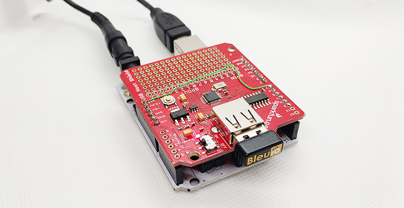
The project is a simple example showcasing a quick way to setup an Arduino with a USB Host Shield as a USB CDC Host capable of communicating with the BleuIO Dongle.
When a BleuIO Dongle is connected to the USB port, the BleuIO Dongle will start advertising. It will then act as a terminal, taking input and sending data to the Arduino Virtual Com Port.
We have used an Arduino Uno Rev. 3 with SparkFun’s USB Host Shield (DEV-09947) for this example.
The largest possible max.packet size for the function Acm.RcvData() is 64 bytes, so to accommodate the amount of data we will receive, we are using three buffers to receive the data from the BleuIO Dongle.
If the buffers have received any data, we print it out to the serial terminal connected to the Virtual COM Port.
void loop()
{
    Usb.Task();

    if( Acm.isReady()) {
       uint8_t rcode;
       uint8_t rcode2;
       uint8_t rcode3;

       /* reading the keyboard */
       if(Serial.available()) {
         uint8_t data= Serial.read();
         /* sending to the BleuIO Dongle */
         rcode = Acm.SndData(1, &data);
         if (rcode)
            ErrorMessage<uint8_t>(PSTR("SndData"), rcode);
       }//if(Serial.available()...

        if(start_flag == 0x00)
        {
            rcode = Acm.SndData(strlen((char *)START_CMDS), (uint8_t *)START_CMDS);
            if (rcode)
            {
                ErrorMessage<uint8_t>(PSTR("SndData"), rcode);
            }

          start_flag = 0x01;
        }
        /* reading the BleuIO Dongle */
        uint8_t  buf[64];
        uint16_t rcvd = 64;
        uint8_t  buf2[64];
        uint16_t rcvd2 = 64;
        uint8_t  buf3[64];
        uint16_t rcvd3 = 64;
        uint8_t  dongle_input[3*64];
        uint16_t input_indx = 0;

        memset(dongle_input, 0, sizeof(dongle_input));

        rcode = Acm.RcvData(&rcvd, buf);
        delay(1);
        rcode2 = Acm.RcvData(&rcvd2, buf2);
        delay(1);
        rcode3 = Acm.RcvData(&rcvd3, buf3);
         if (rcode && rcode != hrNAK)
         {
            ErrorMessage<uint8_t>(PSTR("Ret"), rcode);
         }

         if (rcode2 && rcode2 != hrNAK)
         {
             ErrorMessage<uint8_t>(PSTR("Ret"), rcode2);
         }

         if (rcode3 && rcode3 != hrNAK)
         {
             ErrorMessage<uint8_t>(PSTR("Ret"), rcode3);
         }


            if( rcvd ) { //more than zero bytes received
              for(uint16_t i=0; i < rcvd; i++ ) {
                Serial.print((char)buf[i]); //printing on the screen
                dongle_input[input_indx] = buf[i];
                input_indx++;
              }
            }

            if( rcvd2 ) { //more than zero bytes received
              for(uint16_t i=0; i < rcvd2; i++ ) {
                Serial.print((char)buf2[i]); //printing on the screen
                dongle_input[input_indx] = buf2[i];
                input_indx++;
              }
            }

            if( rcvd3 ) { //more than zero bytes received
              for(uint16_t i=0; i < rcvd3; i++ ) {
                Serial.print((char)buf3[i]); //printing on the screen
                dongle_input[input_indx] = buf3[i];
                input_indx++;
              }
            }
            dongle_input[input_indx] = 0x00;

            // Example on a way for the Arduino to react to BleuIO events
            if(strlen((char *)dongle_input) != 0)
            {
              if(strstr((char *)dongle_input, "handle_evt_gap_connected") != NULL)
              {
                Serial.print("<<CONNECTION DETECTED!>>");
              }
              else if(strstr((char *)dongle_input, "handle_evt_gap_disconnected") != NULL)
              {
                Serial.print("<<CONNECTION LOST!>>");
              }
            }
    }//if( Usb.getUsbTaskState() == USB_STATE_RUNNING..
}
We also store the latest data from the dongle into the dongle_input buffer and run it through a simple “parser” to showcase an easy way of how you can react to events and have the Arduino do something.
In this example, we are explicitly looking for BLE connection or disconnect events. When found, we just print out “<<CONNECTION DETECTED!>>” or “<<CONNECTION LOST!>>” to the terminal.
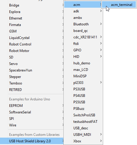
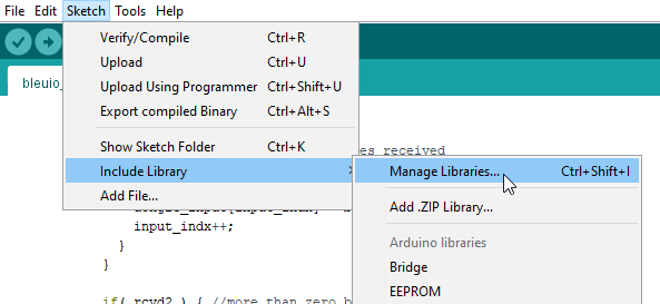
In Arduino IDE choose Sketch>Include Library>Manage Library
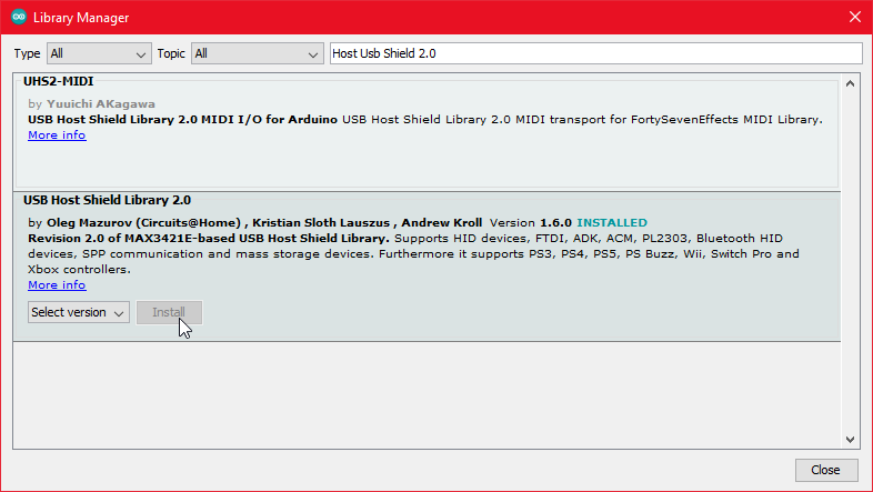
Search for USB Host Shield Library 2.0 and click ‘Install’
5. Running the example
In Arduino IDE click the upload button to upload the project to your Arduino.
Open up the ‘Arduino Uno Viritual COM Port’ with a serial terminal emulation program like TeraTerm, Putty or CoolTerm.Serial port Setup: Baudrate: 115200 Data Bits: 8 Parity: None Stop Bits: 1 Flow Control: None
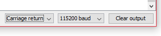
Or inside the Arduino IDE open up Arduino Monitor and in the bottom right corner select ‘Carriage Return’ and ‘115200 baud’
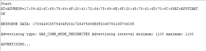
You should see the word ‘Start’ and then see the dongle running two commands: setting response data and starting the advertising. You can now type commands to the dongle.
The project is a simple example showcasing a quick way to set up a STM32Cube project as a USB CDC Host capable of communicating with the BleuIO Dongle.
When a BleuIO Dongle is connected to the Nucleo boards USB port the STM32 will recognize it. It will then accept 3 different inputs from the UART and send one of 3 preprogrammed commands to the BleuIO Dongle based on the input. The commands that are used in this example are:
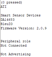
ATI (Dongle Information)
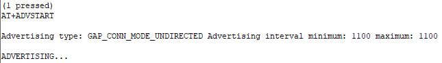
AT+ADVSTART (Starts Advertising)
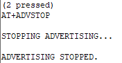
AT+ADVSTOP (Stops Advertising)
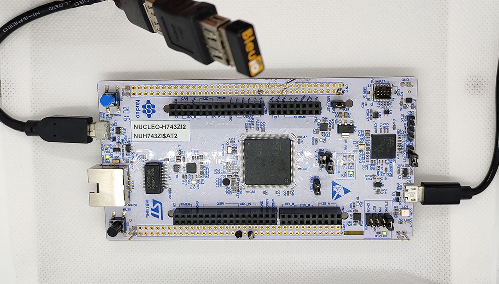
We have used a STM32 Nucleo-144 development board with STM32H743ZI MCU (STM32H743ZI micro mbed-Enabled Development Nucleo-144 series ARM® Cortex®-M7 MCU 32-Bit Embedded Evaluation Board) for this example.
If you want to use another setup you will have to make sure it support USB Host and beware that the GPIO setup might be different and may need to be reconfigured in the .ioc file.
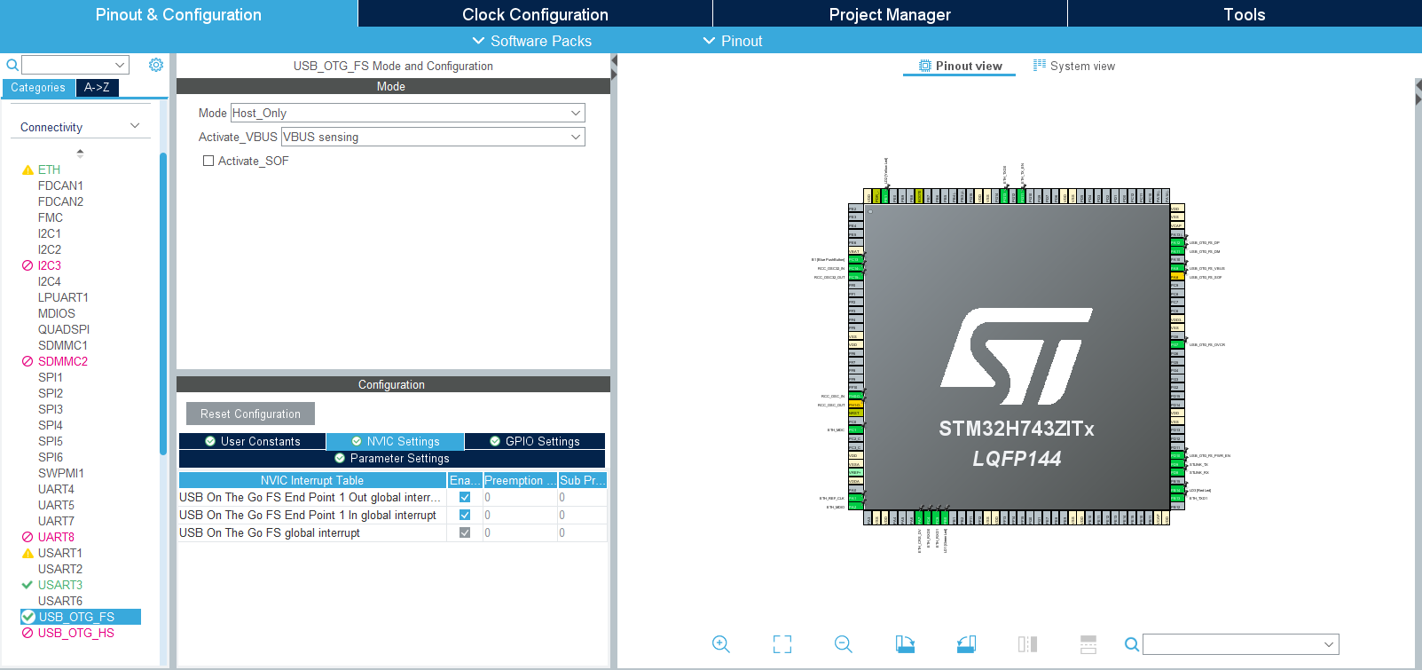
This project based on a new STM32 project with these changes in the .ioc file:
Under ‘Connectivity’ the ‘USB_OTG_FS’-mode is changed to Host_Only and in the NVIC Settings all global interrupts are enabled.
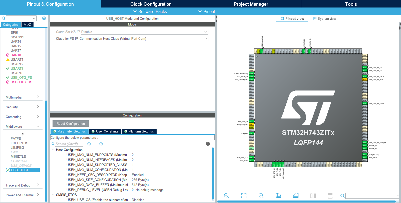
And under ‘Middleware’ the ‘USB_HOST’- ‘Class for FS IP’ is set to ‘Communication Host Class (Virtual Port Com)’.
To make sure the host would recognize when the bootloader is done and the BleuIO firmware is running this was added in the USBH_UserProcess function in ‘usb_host.c’ (found under ‘USB_HOST’ -> ‘App’ folder):
static void USBH_UserProcess (USBH_HandleTypeDef *phost, uint8_t id)
{
/* USER CODE BEGIN CALL_BACK_1 */
switch(id)
{
case HOST_USER_SELECT_CONFIGURATION:
break;
case HOST_USER_DISCONNECTION:
Appli_state = APPLICATION_DISCONNECT;
isBleuIOReady = false;
// Turn on Red LED, turn off Green and Yellow LED
HAL_GPIO_WritePin(GPIOB, GPIO_PIN_0, GPIO_PIN_RESET);
HAL_GPIO_WritePin(GPIOE, GPIO_PIN_1, GPIO_PIN_RESET);
HAL_GPIO_WritePin(GPIOB, GPIO_PIN_14, GPIO_PIN_SET);
break;
case HOST_USER_CLASS_ACTIVE:
Appli_state = APPLICATION_READY;
// Check if BleuIO firmware is running// (idProduct:0x6001 = bootloader, idProduct:0x6002 = bleuio fw)
if(phost->device.DevDesc.idProduct == 0x6002)
{
isBleuIOReady = true;
// Sends message to uart that BleuIO is connected and ready
HAL_UART_Transmit(&huart3, (uint8_t*)BLEUIO_READY, strlen(BLEUIO_READY), HAL_MAX_DELAY);
// Turn on Green LED, turn off Yellow and Red LED
HAL_GPIO_WritePin(GPIOB, GPIO_PIN_0, GPIO_PIN_SET);
HAL_GPIO_WritePin(GPIOE, GPIO_PIN_1, GPIO_PIN_RESET);
HAL_GPIO_WritePin(GPIOB, GPIO_PIN_14, GPIO_PIN_RESET);
// Start receiving from usb
USBH_CDC_Receive(&hUsbHostFS, CDC_RX_Buffer, RX_BUFF_SIZE);
}
break;
case HOST_USER_CONNECTION:
Appli_state = APPLICATION_START;
isBleuIOReady = false;
// Turn on Yellow LED, turn off Green and Red LED
HAL_GPIO_WritePin(GPIOB, GPIO_PIN_0, GPIO_PIN_RESET);
HAL_GPIO_WritePin(GPIOE, GPIO_PIN_1, GPIO_PIN_SET);
HAL_GPIO_WritePin(GPIOB, GPIO_PIN_14, GPIO_PIN_RESET);
break;
default:
break;
}
/* USER CODE END CALL_BACK_1 */
}
The Green, Red and Yellow LEDs on the Nucleo board is also setup to change based on the connection status.
Red = Disconnnected. Yellow = Connecting. Green = Connected.
An external variable bool isBleuIOReady is also set so the status of the dongle is accessible from main.c.
Once the BleuIO dongle is confirmed to be connected the USBH_CDC_Receive function is run to start reciving data from the USB CDC.
The USBH_CDC_ReceiveCallback also needs to be implemented:
void USBH_CDC_ReceiveCallback(USBH_HandleTypeDef *phost)
{
    if(phost == &hUsbHostFS)
    {
        // Handles the data recived from the USB CDC host, here just printing it out to UART
        rx_size = USBH_CDC_GetLastReceivedDataSize(phost);
        HAL_UART_Transmit(&huart3, CDC_RX_Buffer, rx_size, HAL_MAX_DELAY);

        // Reset buffer and restart the callback function to receive more data
        memset(CDC_RX_Buffer,0,RX_BUFF_SIZE);
        USBH_CDC_Receive(phost, CDC_RX_Buffer, RX_BUFF_SIZE);
    }

    return;
}
In this example the recieved data is just echoed to the UART.
To send data to the Dongle the USBH_CDC_Transmit function is used. In this example UART input is used to send different commands.
For this purpose a wrapper function has been created that can be accessed from main.c:
/**
  * @brief Simple function that takes a string and transmit it to the dongle
  * @retval None
  */
void writeToDongle(uint8_t * cmd)
{
    USBH_CDC_Transmit(&hUsbHostFS, cmd, strlen((char *)cmd));
}
In main.c HAL_UART_RxCpltCallback is implemented to recieve input from Uart and a simple UART input handler:
The handleUartInput() handles the inputs 0, 1 and 2 and maps each to a certain Dongle commands. The handler is then put inside the main loop.
/* Infinite loop *//* USER CODE BEGIN WHILE */
while (1)
{
/* USER CODE END WHILE */
MX_USB_HOST_Process();
/* USER CODE BEGIN 3 */// Simple handler for uart input
handleUartInput(uartStatus);
}
/* USER CODE END 3 */
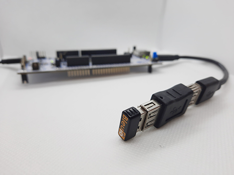
A board with a STM32 Microcontroller with a USB port. (A Nucleo-144 development board: NUCLEO-H743ZI2, was used developing this example. (https://www.st.com/en/evaluation-tools/nucleo-h743zi.html) To connect the dongle to the Nucleo board a “USB A to Micro USB B”-cable with a USB A female-to-female adapter can be used.)
Either clone the project, or download it as a zip file and unzip it, into your STM32CubeIDE workspace.
4.2 Importing as an Existing Project
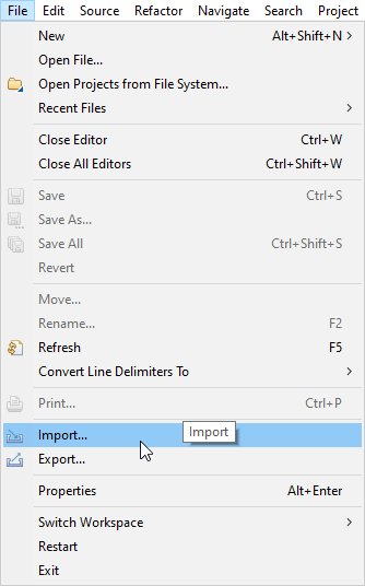
From STM32CubeIDE choose File>Import…
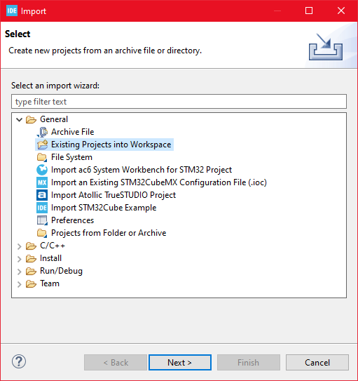
Then choose General>Existing Projects into Workspace then click ‘Next >’
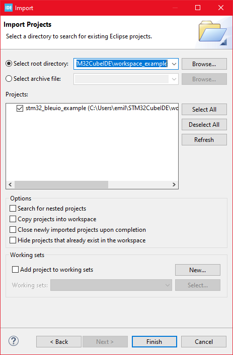
Make sure you’ve choosen your workspace in ‘Select root directory:’
You should see the project “stm32_bleuio_example”, check it and click ‘Finish’.
5. Running the example
In STMCubeIDE click the hammer icon to build the project.
Open up the ‘STMicroelectronics STLink Virtual COM Port’ with a serial terminal emulation program like TeraTerm, Putty or CoolTerm.Serial port Setup: Baudrate: 115200 Data Bits: 8 Parity: None Stop Bits: 1 Flow Control: None
In STMCubeIDE click the green play button to flash and run it on your board. The first time you click it the ‘Run Configuration’ window will appear. You can just leave it as is and click run.
Connect the BleuIO Dongle.
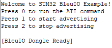
Wait until the message: “[BleuIO Dongle Ready]” is shown.
– Press 0 to get device information:
– Press 1 to start advertising:
– Press 2 to stop advertising:
BlueIO dongle responses will be printed out to Virtual COM Port.
Suppose you have some BLE devices at your home and want to control or scan for those devices while at your workplace. In this project, we will discuss how to access BLE data remotely.
We have already created a script that communicates through BleuIO dongle remotely and gives us the response. You can access the script at
You are free to clone the script and make changes as you wish.
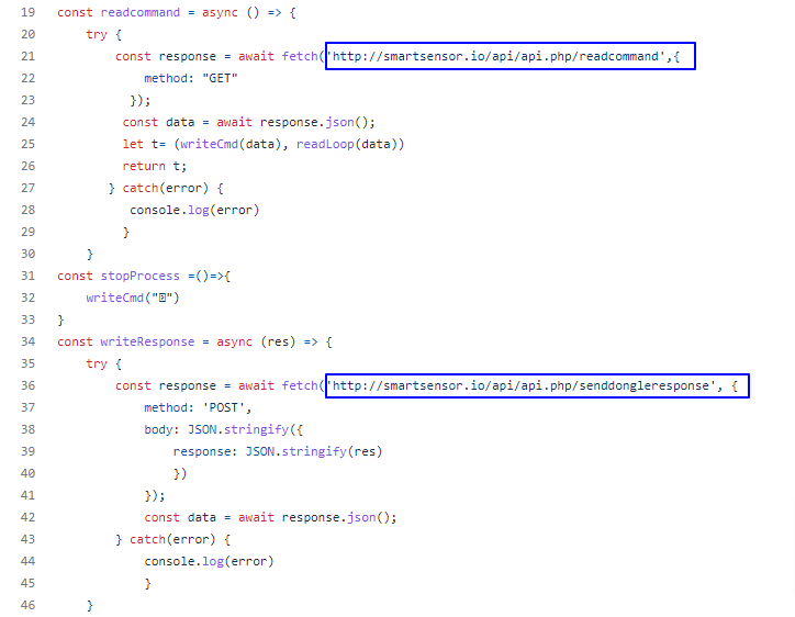
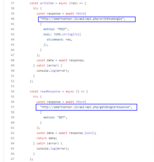
In this script, JavaScript is used to connect to the dongle using google chrome’s serial port. There is a simple PHP script that helps pass data through the cloud.
Step 1: Uploading
Upload the API folder in any server that supports PHP. This script reads and writes data to a JSON file upon request.
We have uploaded the file at http://smartsensor.io/api/api.php
You can use this URL if you don’t have a server to upload.
Step 2: Home computer setup
Open the index.js file found in the root folder and update the URL of the API file on both occasions.
You can leave the url as it is if you want to use file from our server.
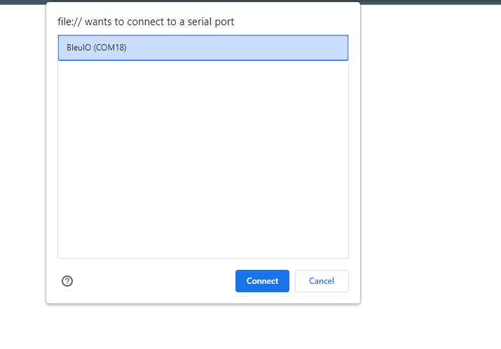
Now connect a BleuIO dongle to your home computer and open the index.html file from the root folder.
Click connect and select the COM port where the dongle is connected.
Open the index.html file found in the user folder and update the URL of the API file on both occasions.
You can leave the url as it is if you want to use file from our server.
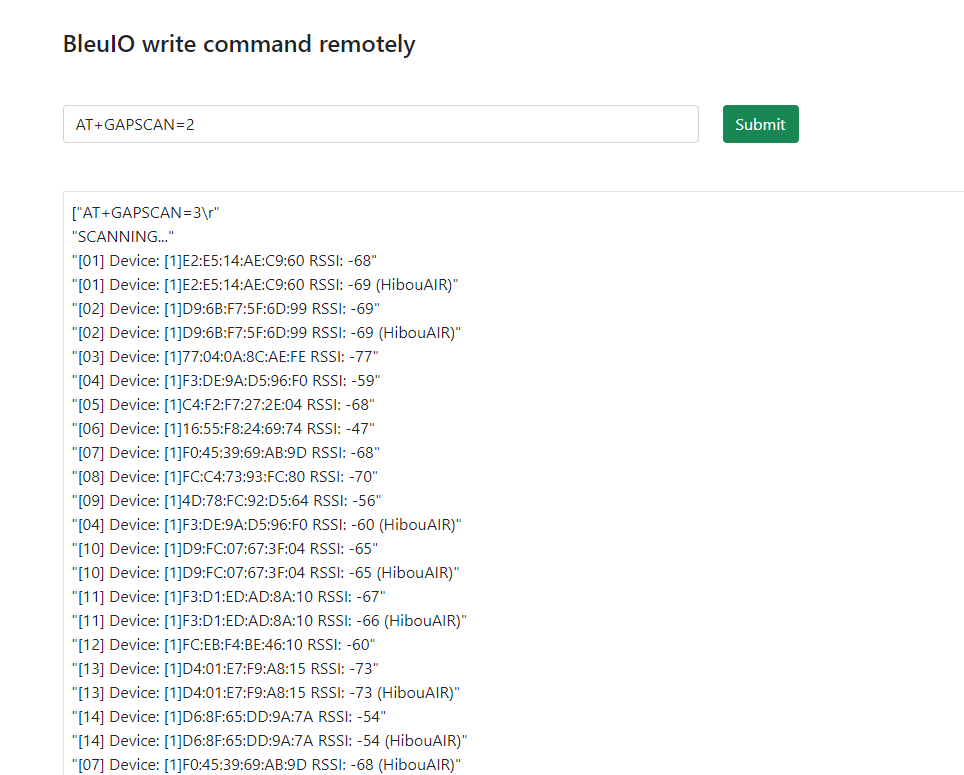
Now open this file in a browser and start writing AT commands.
Currently, You can access the following AT commands
ATI ( Returns firmware version, hardware type and unique organization identifier, device connection status )
AT+CENTRAL (Sets the device Bluetooth role to central role.)
AT+PERIPHERAL (Sets the device Bluetooth role to the peripheral.)
AT+DUAL (Sets the device Bluetooth role to dual role. Which means it has both Central and Peripheral role capabilities.)
AT+ADVSTART (Starts advertising)
AT+ADVSTOP (Stops advertising. Returns ERROR if not already advertising)
AT+GAPSTATUS (Reports the Bluetooth role)
AT+GAPSCAN=2 (Starts a Bluetooth device scan with the timer set in seconds. Make sure to set a timer for the scan.)
Once you type one of the above commands, you will start to see the response from the dongle on your browser screen.
I am trying to scan for BLE devices at my home where BleuIO dongle is connected. Here I got a list of devices showing on my browser screen. Make sure the device is on central mode to scan for devices.
You can add more AT commands to the script as required. All you need to do is update the index.js file found in the root folder.
Find the list of AT commands our from getting started guide at
BleuIO released a new firmware version 2.0.9 on November 05, 2021, introducing new features and enhancements to improve productivity. You can download the updated firmware from
Following features and AT commands has been added to this release
Added features:
Added support to set the information in the Device Service Information (DIS).
Added Commands
Added a new command AT+DIS, that is used to view current information used in the Device Information Service (DIS).
Added a new command AT+SETDIS that is used to set current information used in the Device Information Service (DIS).
What is Device information service?
Device information service exposes manufacturer and/or vendor information about a device. It is a very good way for the maker of equipment, software and hardware version control, production information disclosure. It is therefore recommended to include this Standard service defined by the Bluetooth SIG at the time of development.
Use the following AT command to set Device information service
The Manufacturer Name String characteristic shall represent the name of the manufacturer of the device.
Model Number String
The Model Number String characteristic shall represent the model number that the device vendor assigns.
Serial Number String
The Serial Number String characteristic shall represent the serial number for a particular instance of the device.
Hardware Revision String
The Hardware Revision String characteristic shall represent the hardware revision for the hardware within the device.
Firmware Revision String
The Firmware Revision String characteristic shall represent the firmware revision for the firmware within the device.
Software Revision String
The software Revision String characteristic shall represent the software revision for the software within the device.
Note that information can only be set before starting advertising. If no custom information is set, the default BleuIO device information will be used. Once advertising is started, the information set to be used will be locked in and cannot be changed during runtime.
To change the device information again, the dongle will need to be restarted, either by unplugging it and plugging it back in or using the ATR command.
Max length is 100 characters per parameter.
Use the AT+DIS AT command to view current Device Information Service to be used. It Will show the default BleuIO information if no custom information has been set.